Do you have a question about the BEP MARINCO 771-S-EZ and is the answer not in the manual?
Highlights ease of mounting, cabling flexibility, durability, and high-quality construction for marine environments.
Details continuous, intermittent, and cranking ratings, connection stud size, voltage, IP rating, and certifications.
Read before installing. Electrical terminations by technician recommended. Not for switching under load.
Step-by-step guide for mounting the switch base, connecting cables, and securing the actuator.
Procedure for removing and replacing the actuator, ensuring the switch is in the 'OFF' position.
Verification steps to confirm correct functionality in different switch positions.
Provides physical measurements for surface and rear panel mounting of the switch.
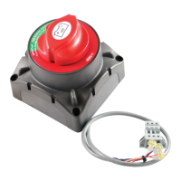
The Marinco BEP Products EZ Mount Selector Battery Switch is a robust and versatile device designed for isolating and managing battery power in marine environments. It is available in two retail packages: the 771-S-EZ 400A EZ Mount Selector (Retail Packed) and the 771-S-EZ-B (Bulk Packed). This switch is engineered for ease of installation and integration with other Pro Installer Busbar Range components, offering a compact and efficient solution for electrical systems.
The primary function of the EZ Mount Selector Battery Switch is to provide a means of isolating and selecting battery banks. It allows users to connect to Battery 1, Battery 2, or both (1&2), and to completely disconnect power (OFF). This capability is crucial for maintenance, safety, and managing power distribution from multiple battery sources. The switch is designed for surface mounting, allowing for front access to wiring, which simplifies installation and maintenance. It is intended for isolation purposes and should not be used for switching under load, meaning the engine or other high-current devices should be off before changing the switch position. The device also features a removable knob for enhanced security and safety, preventing accidental or unauthorized operation.