EN / BEP Smart Battery Hub User Installation Manual
Voltage Sensitive Switch Settings ........................................................................................................ 19
Dipswitches .......................................................................................................................................... 20
CZone Configuration ............................................................................................................................ 22
CZone Configuration Tool .................................................................................................................... 22
Configuration via USB .......................................................................................................................... 24
MULTIPLE SMART BATTERY HUB INSTALLATIONS .............................................................. 25
SPECIFICATIONS ........................................................................................................................ 26
Technical Specifications ....................................................................................................................... 26
Dimensions .......................................................................................................................................... 27
ORDERING INFORMATION ......................................................................................................... 26
CE DELCARATION OF CONFORMITY ....................................................................................... 29
Table Of Figures
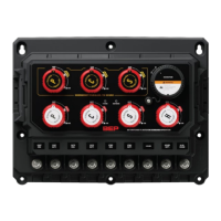
Figure 1. SBH Smart Battery Hub Overview ............................................................................................................. 6
Figure 2. Exploded Mounting View ......................................................................................................................... 11
Figure 3 Twin Engine Connections ......................................................................................................................... 12
Figure 4. Triple engine connections ........................................................................................................................ 13
Figure 5. Twin engine internal wiring ...................................................................................................................... 14
Figure 6. Triple engine internal wiring ..................................................................................................................... 14
Figure 7. External Temperature Sensor ................................................................................................................. 15
Figure 8. Connector Pin Out ................................................................................................................................... 16
Figure 9. Default Switch / SI Input .......................................................................................................................... 18
Figure 10. Optional Switch / SI Input ...................................................................................................................... 18
Figure 11. Multiple Engine Installation .................................................................................................................... 25
Figure 12. Dimensions ............................................................................................................................................ 28


 To Next Page