ENGLISH
6
The boiler automatically adapts ventilation according to the type
of installation and the length of the duct.
It is compulsory to use specic pipes.
Make sure the ue gas discharge pipe is tilted 3° towards the
boiler.
Do not obstruct or choke the combustion air suction pipe in any
way.
For installation, follow the instructions supplied with the kit.
pipe length
Ø 80 (m)
air ange
pressure drops for
each bend (m)
45° 90°
25 C.S.I.
from 0.5 to 7 Ø 40
1 1.5
from 7 to 13.5 Ø 45
from 13.5 to 19.5 not installed
29 C.S.I.
from 0.5 to 5 Ø 45
1 1.5
from 5 to 12 not installed
POSSIBLE OUTLET CONFIGURATIONS (fig. 21)
B22P/B52P - Suction in room, with external discharge.
C12-C12x - Concentric discharge on wall. Pipes can leave the boiler
independently, but the outputs must be concentric or near enough in
order to be subjected to similar wind conditions (within 50 cm).
C22 - Concentric discharge in regular smoke pipe (suction and dis-
charge in the same pipe).
C32-C32x - Concentric discharge on the roof. Outputs as C12.
C42-C42x - Discharge and suction in regular smoke pipes (separated
but subject to similar wind conditions).
C52-C52x - Separated discharge and suction on wall or roof, in areas
with different pressure levels. The discharge and suction lines must
never be placed on opposite walls.
C62-C62x - Discharge and suction using pipes marketed and certified
separately (1856/1).
C82-C82x - Discharge in a single or regular smoke pipe, and suction
on the wall.
C92-C92x - Discharge on roof (similar to C32) and air suction via a
single existing smoke pipe.
Refer to the regulations in force.
For the indication of the maximum lengths of the single pipe, refer to
the following charts.
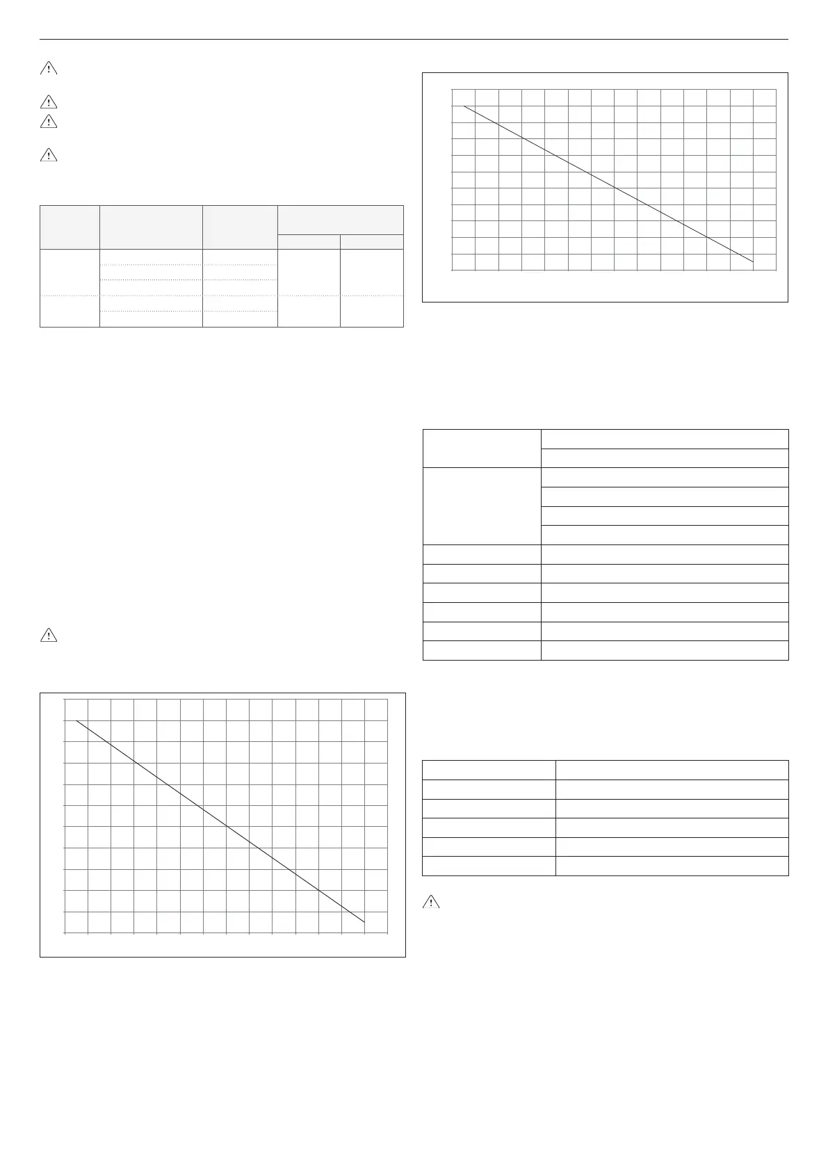
25 C.S.I.
air suction pipe length (m)
0
2
4
6
8
10
12
14
16
18
20
22
0 246810121416182022242628
ue gas pipe length (m)
29 C.S.I.
0
2
4
6
8
10
12
14
16
18
20
22
0 246810121416182022242628
ue gas pipe length (m)
air suction pipe length (m)
Twin pipes ø 80 with ducting Ø 60 (g. 22)
Thanks to the boiler characteristics, a ue gas discharge pipe Ø 80 can
be connected to the ducting ranges Ø 60.
For the ducting, you are advised to make a project calculation in order
to respect the relevant standards in force.
The table shows the standard congurations allowed.
Table of standard pipe congurations (*)
Air suction
1 bend - 90° ø 80
4.5m pipe ø 80
Flue gas discharge
1 bend - 90° ø 80
1m pipe ø 80
Reduction from ø 80 to ø 60
1 T-fitting ø 60
25 C.S.I.
Flange Ø 40 5m pipe ø 60 vertical
Flange Ø 45 9m pipe ø 60 vertical
No flange 17m pipe ø 60 vertical
29 C.S.I.
No flange 5m pipe ø 60 vertical
(*) Use ue gas system accessories in plastic (PP) for condensing boilers.
The congurations Ø 60 show test data veried in the laboratory.
In the case of installations that differ from those indicated in the “stand-
ard conguration” tables, refer to the equivalent linear lengths Ø 80 - Ø
60 below.
COMPONENT Ø 60
Linear equivalent in metres Ø80 (m)
Bend 45° Ø 60
5
Bend 90° Ø 60
8
Extension 0.5m Ø 60
2.5
Extension 1.0m Ø 60
5.5
Extension 2.0m Ø 60
12
In any case, the maximum lengths declared in the booklet are
guaranteed, and it is essential not to exceed them.
3.9 Filling the heating system (fig. 23)
Once the hydraulic connections have been carried out, ll the heating
system.
This operation must be carried out with a cold system, following these
instructions:
- open the automatic air vent valve cap (A) by two or three turns
- make sure the cold water inlet tap is open
- open the lling tap (B) until the pressure indicated by the water pres-
sure gauge is between 1 and 1.5 bar.
Once lling is complete, close the lling tap.
The boiler has an efcient air separator so no manual intervention is
needed.
 Loading...