10
4.6 Condensate outlet
The condensate water produced by
Power Plus Box P INT-
EXT
a normal running conditions is evacuated into a spe-
cial manifold.
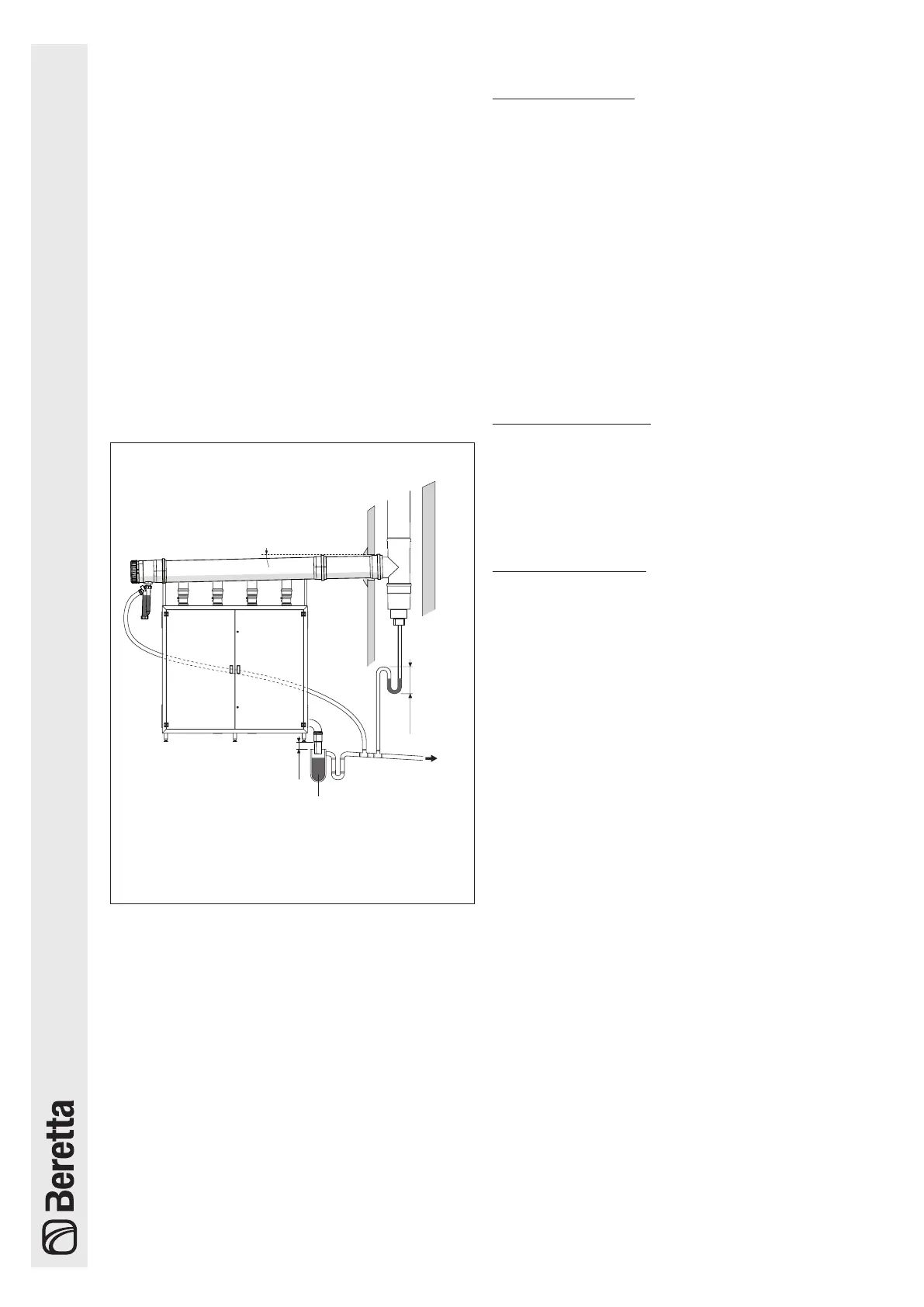
Drainage must be done at atmospheric pressure, i.e. by
dripping into a connected drain-trap, as follows:
- install a drip at the condensate drainage manifold;
- connect the drip to the sewerage mains by a drain-
trap;
- be ready to use a neutralizer where required (see pro-
ject cig E.01.08.929.0; ATV A 115).
There is generally no need to take any special precautions
for draining condensate.
We advise using plastic (PP) piping for building the con-
densate drainage.
a
DO NOT for any reason use pipes in copper or in any
other material not specifically used for this particular
scope, as the condensing action could cause rapid
degradation.
(*)
(*)
i > 3%
i
i ≥ 3°
Condensate collector
(*) Fill the siphons with water.
(at atmospheric pressure)
Civil drain
minimum
distance
300 mm
minimum
distance
10 mm
Fig. 7
Furthermore, should the vertical part of the flue exhaust
duct have to be prolonged by more than 4 metres the con-
densate drain-trap will have to be placed at the foot of the
piping. The working height of the drain-trap must be at
least 30 cm. The drain-trap outlet must then be connected
up to the sewerage mains.
b
The condensate drain must be connected to the sew-
erage mains in such way as to prevent it from being
frozen under any circumstances.
b
Always install a condensate drain in the exhaust flue
duct at no more than 1 m from the boiler
4.7 Water circuit
WORKING PRESSURE
The maximum working pressure of the boiler is 6 bar (600
kPa) whilst the minimum is 0.5 bar (50 kPa).
b
It is compulsory to install devices along the topping
up/supply line as well as the water circulation system
to protect the installation from pressures exceeding
550 kPa, in conformity to prescriptions given in the
EN 60335-2-102.
b
Do not expose the exchanger to cyclic changes in
pressure as fatigue stress does a lot of harm to the
system components. Should the water system sud-
denly start generating changes in pressure it is com-
pulsory to use the protection devices to make the
boiler work at a regular pressure.
b
Installation pressure control must be done under cold
conditions.
FILLING UP THE BOILER
The boiler must be filled up by connecting the water from to
the mains to any part of the installation.
b
It is compulsory to use a standard filling device
(EN61770 type) for coupling up to the mains specifi-
cally preventing the back-flow of liquid from installa-
tion to water mains.
EMPTYING THE BOILER
Emptying of the system is made by acting on the discharge
valves of each unit and in some points of the hydraulic sys-
tem specific for this purpose.
For more information on the characteristics of hydraulic
system see Chapter 5 in which different types of plant are
shown.
4.8 Exhaust ue
The chimney should be as straight as possible, sealed and
isolated. Should not have occlusions or narrowing.
b
The overall potential of thermal groups
Power Plus
Box P INT-EXT
Series is more than 35 kW, so they can
be installed only in rooms that have venting opening
to the outside according to actual law (italian D.M.
12.04.1996).
b
The
Power Plus Box P INT-EXT
series generators must
be connected to a exhaust pipe system in flame re-
tardant polypropylene (PP) or suitable materials ac-
cording to UNI EN 677 and associated standards.
a
DO NOT for any reason use piping not specifically
designed for this specific scope as the condensing
action could cause rapid degradation.
b
Where collectors are used to evacuate the smoke, the
presence of non-return valves within each unit stops
the products of combustion of the active units enter-
ing the boiler room by means of the closed unit intake
ducts.
a
In the event of installation with air intake from the
premises (both in the heating unit and externally)
avoid obstructing the passage of air under the metal
cupboard.
 Loading...