This manual, Code 20074299 - Rev. 6 (02/18) comprises 44 pages.
2
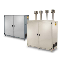
RANGE
MODEL CODE
Power Plus Box 1002 P INT 20067829
Power Plus Box 1003 P INT 20067830
Power Plus Box 1004 P INT 20067831
Power Plus Box 1002 P EXT 20067832
Power Plus Box 1003 P EXT 20067833
Power Plus Box 1004 P EXT 20067834
Power Plus Box 1002 P INT ERP 20107464
Power Plus Box 1003 P INT ERP 20107472
Power Plus Box 1004 P INT ERP 20107478
Power Plus Box 1002 P EXT ERP 20107469
Power Plus Box 1003 P EXT ERP 20107477
Power Plus Box 1004 P EXT ERP 20107479
CERTIFIED COMPANY
UNI EN ISO 9001:2008
UNI EN ISO 14001:2004
This manual, Code
- Rev.
comprises
pages.
ENGLISH
CONTENTS
The following symbols are used in this manual:
b
CAUTION! =
Identifies actions that require caution
and adequate preparation.
a
STOP! =
Identifies actions that you MUST NOT do.
1 GENERAL INFORMATION ................3
2 WARNINGS ............................3
3 TECHNICAL FEATURES .................4
3.1 Main features ............................4
3.2 Advantages.............................. 5
3.3 Safety devices............................ 5
3.4 Components ............................. 5
4 INSTALLATION.........................8
4.1 Product packaging and identification.......... 8
4.2 Installation premises .......................8
4.3 Water connections ........................ 9
4.4 System cleaning and water treatment.......... 9
4.5 Positioning and preparation for installation......9
4.6 Condensate outlet........................ 10
4.7 Water circuit ............................10
4.8 Exhaust flue............................. 10
5 INSTALLATION DIAGRAMS .............11
6 ELECTRICAL SYSTEM .................12
6.1 Power supply ........................... 12
6.2 Electrical connections..................... 12
6.2.1 Connection to mains ......................12
6.2.2 Master board connection ..................13
6.2.3 Connection to thermoregulators ............. 14
6.2.4 Connection to pumps ..................... 14
6.2.5 Connection to room thermostats (on/off) ......14
6.2.6 Connection to weather temperature probe..... 14
6.2.7 Frost protection .......................... 16
6.2.8 Connection to 0-10v external thermoregulator .. 16
6.2.9 Connection to alarm device ................ 16
6.2.10 Remote control .......................... 16
6.3 Emergency mode ........................ 16
6.4 Cascade installation ...................... 17
6.4.1 Connection to mains ......................17
6.4.2 Serial Connection (BUS) ...................17
6.5 Position of the flow probe ..................17
7 FIRST OPERATING ....................18
7.1 Slave board setting ....................... 18
7.1.1 Example of configuretion of a battery with 7 burner
in cascade ............................. 18
7.2 Gas valve calibration ..................... 19
8 USE AND ADJUSTMENT ................20
8.1 Control panel: description.................. 20
8.2 Display mode ........................... 21
8.3 Display mode ........................... 21
8.4 Changing the user parameters .............. 22
8.5 Monitor mode ........................... 22
8.6 Installer programming mode................23
8.7 Test mode .............................. 24
8.8 Error mode .............................24
8.9 Permanent block ......................... 24
9 SETTING FUNCTIONING PARAMETERS ...25
9.1 Setting the heating parameters.............. 25
9.2 Setting the DHW parameters ............... 26
9.3 Heat control setting....................... 27
10 LIST OF PARAMETERS .................32
11 ERROR LIST ..........................34
11.1 Master board errors ...................... 34
11.2 Slave board errors........................ 34
12 WIRING DIAGRAMS....................36
13 TECHNICAL SPECIFICATIONS ...........38
14 WATER IN CENTRAL HEATING SYSTEMS . 40
 Loading...