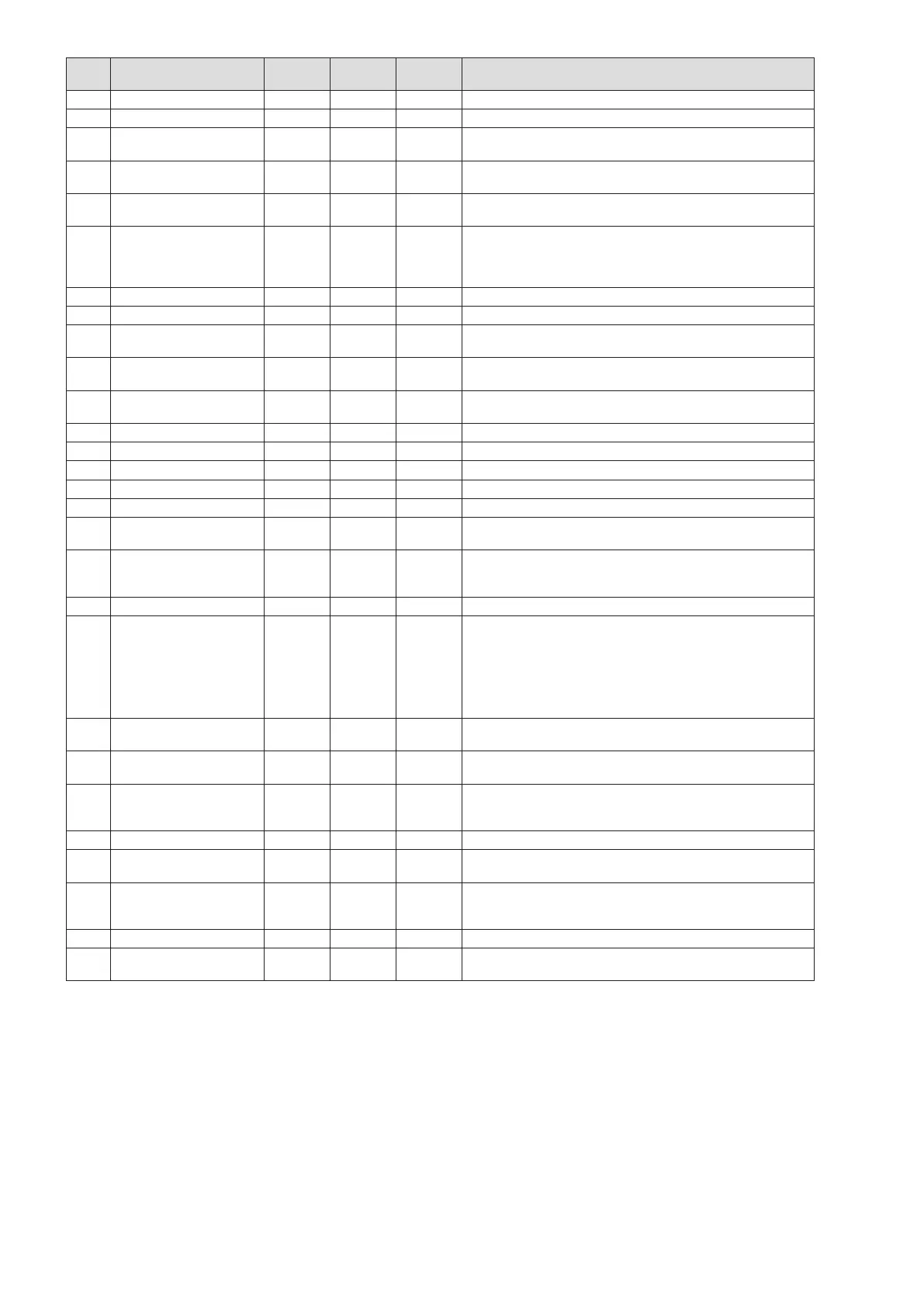
33
Nr. Parameter name
Factory
setting
Lower
limit
Upper
limit
Description
17 CH1 max. Temp. 80°C 10°C 80°C Max. settable value for high system
18 CH1 min. Temp. 50°C 10°C Par.1 Min temp. value high system (at max. external T.).
19 CH1 ON diff. 7°C 0°C 20°C
Burner re-ignites after said differential.
E.g.: 70°C – 7°C = 63°C
20 CH1 OFF diff. 3°C 0°C 20°C
The burner goes out after said differential.
E.g.: 70°C+3°C= 73°C
21 CH1 attenuation 0°C 0°C 70°C
Ch1 temp. attenuation (par.1) only if the high tempera-
ture system thermostat is on.
22 CH2 adjustment 1 0 3
0 = Temperature at fixed point.
1 = Weather with probe outside
2 = 0–10V: power (Acts on power)
3 = 0-10V:temperature (Acts on temperature)
23 CH2 max. Temp. 50°C 10°C 70°C Max. set heating value low system.
24 CH2 min. Temp 25°C 10°C Min temp. value low system (at max. external T.)
25 CH2 attenuation 0°C 0°C 70°C
Ch2 temp. attenuation (par.3) only if the low tempera-
ture system thermostat is on.
26 CH2 ON diff. 5°C 0°C 20°C
Burner re-ignition differential below low temp. system
setpoint
27 CH2 OFF diff. 3°C 0°C 20°C
Burner burn out differential exceeding low temp. sys-
tem setpoint
28 Mix valve on time 5 sec 0 sec 255 sec Mixer valve opening time
29 Mix valve off time 7 sec 0 sec 255 sec Mixer valve closing time
30 Mix valve stop T 5 sec 0 sec 255 sec Mixer valve stand-by time
31 Mix valve on-off diff 2°C 0°C 30°C Mixer valve open/closed differential
32 Mix valve stop diff. 2°C 0°C 30°C Mixer valve stand-by differential
33 Power control 1 0 1
0 = power distributed over min. number burners
1 = power distributed over max. number burners
34 Pump mode 0 0 1
Third pump setpoint:
0 = Main pump of system/loop
1 = Low temperature pump
35 Anti-freeze 3°C -30°C 15°C Initial temp. for frost protection (NB1)
36 Gas type 1 1 7
1 = Methane with exhaust flue < 15m
2 = Methane with exhaust flue > 15m
3 = LPG with exhaust flue < 15m
4 = LPG with exhaust flue > 15m
5 = Town Gas
6 = Gas F
7 = Gas G
37 Min. outside T. 0°C -20°C 30°C
Min external temperature (provides max. flow tempera-
ture value setting)
38 Max outside T. 18°C 0°C 30°C
Max external temperature (provides min. flow tempera-
ture value setting)
38.
Outdoor Temperature
summer/winter function
0°C 0°C 30°C
Outdoor temperature above which heating circuit
requests are deactivated
0= function not activated
39 Correction Text 0°C -30°C 30°C External temperature corrector factor
40 Emergency T. 70°C 10°C 80°C
Emergency temperature of slave if the Master breaks
down.
41
Parameter reset
0 0 1
1 = Slave reset to factory parameters.
N.B. Parameter 36 (gas type) is not changed by reset-
ting factory parameters
42 Flowmeter 1 0 1 0 = slave fails to check the flowmeter
43 Protocol 1 0 1
0 = Eco protocol
1 = Argus link
PARAMETER 35 - FROST PROTECTION
The third pump will start up if the outside temperature is lower than parameter 35 (Frost protection) or if the flow tem-
perature is lower than 5°C. If after 10 minutes the T1 fails to exceed 5°C, a burner will start up at maximum power until
T1 exceeds 20°C. If after 10 minutes the T4 is still below parameter 35 but T1 exceeds 5°C the pump will work until T4
exceeds parameter 35.
 Loading...