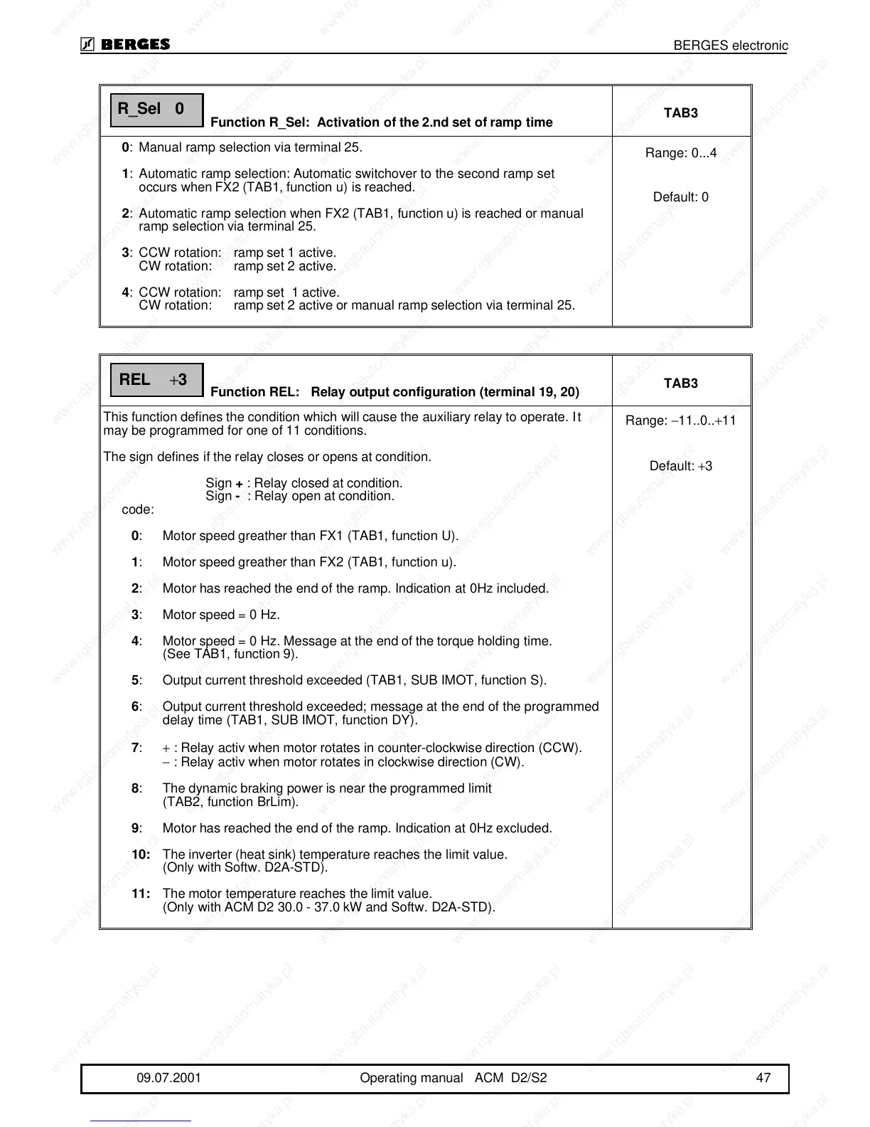
Function R_Sel: Activation of the 2.nd set of ramp time
TAB3
0:Manual ramp selection via terminal 25.
1:Automatic ramp selection: Automatic switchover to the second ramp set
occurs when FX2 (TAB1, function u) is reached.
2:Automatic ramp selection when FX2 (TAB1, function u) is reached or manual
ramp selection via terminal 25.
3:CCW rotation: ramp set 1 active.
CW rotation: ramp set 2 active.
4:CCW rotation: ramp set 1 active.
CW rotation: ramp set 2 active or manual ramp selection via terminal 25.
Range: 0...4
Default: 0
Function REL: Relay output configuration (terminal 19, 20)
TAB3
This function defines the condition which will cause the auxiliary relay to operate. It
may be programmed for one of 11 conditions.
The sign defines if the relay closes or opens at condition.
Sign + : Relay closed at condition.
Sign - : Relay open at condition.
code:
0: Motor speed greather than FX1 (TAB1, function U).
1: Motor speed greather than FX2 (TAB1, function u).
2: Motor has reached the end of the ramp. Indication at 0Hz included.
3: Motor speed = 0 Hz.
4: Motor speed = 0 Hz. Message at the end of the torque holding time.
(See TAB1, function 9).
5: Output current threshold exceeded (TAB1, SUB IMOT, function S).
6: Output current threshold exceeded; message at the end of the programmed
delay time (TAB1, SUB IMOT, function DY).
7: + : Relay activ when motor rotates in counter-clockwise direction (CCW).
− : Relay activ when motor rotates in clockwise direction (CW).
8: The dynamic braking power is near the programmed limit
(TAB2, function BrLim).
9: Motor has reached the end of the ramp. Indication at 0Hz excluded.
10:The inverter (heat sink) temperature reaches the limit value.
(Only with Softw. D2A-STD).
11:The motor temperature reaches the limit value.
(Only with ACM D2 30.0 - 37.0 kW and Softw. D2A-STD).
Range: −11..0..+11
Default: +3
R_Sel 0
REL
+
3
BERGES electronic
09.07.2001 Operating manual ACM D2/S2 47