ELECTRIC C301 - DIAGNOSTICS & TROUBLESHOOTING - GB
5
ELECTRIC C301 - DIAGNOSTICS & TROUBLESHOOTING
The machine controller detects a wide variety of faults or errors.
Diagnosc informaon can be obtained on the 3100R fuel gauge display where an error code in the format ''Err ##''.
The troubleshoong chart below describes the Error code faults and their possible causes.
Whenever a fault is encountered the rst acon should be to turn o the ignion and push in the E stop buon. Then pull out the E stop buon and turn the ignion back
on to see if the fault clears. This is the RESET procedure:.
If the Error code does not clear aer the machine RESET, turn o the ignion switch and remove the 35-pin connector. Check the connector for correcon or damage,
clean it if necessary, and reinsert it.
If the Error is sll seen then the wiring and connecons on the machine should be checked for breakages or loose connecons.
The table below should be used as a reference once the above checks have been carried out.
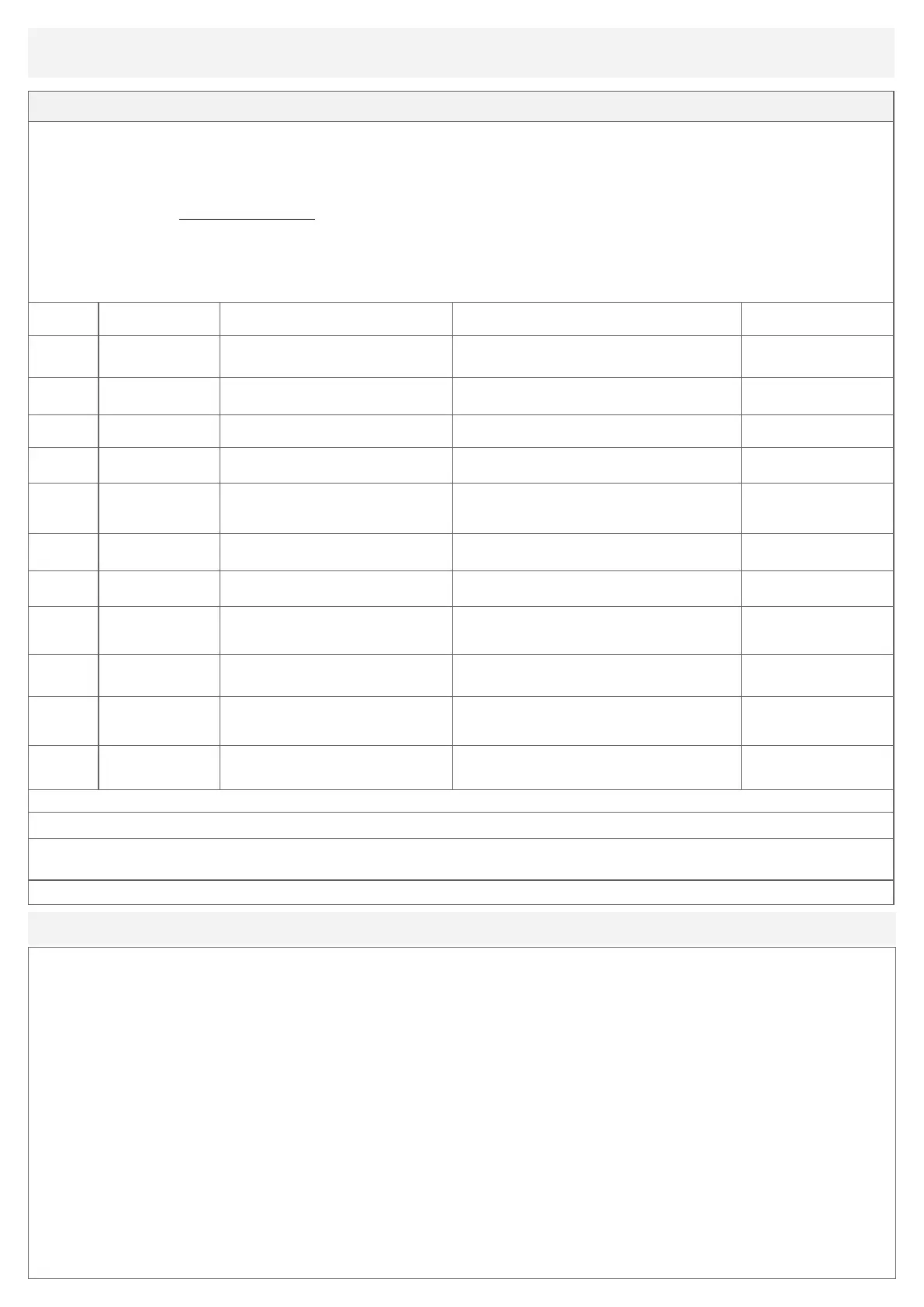
Error code Descripon of Error
Possible Cause /
Reason for Error
Check points
Technical Bullen
(see website)
1
HW
Fail-safe
Motor fault voltage (hardware failure)
1. Motor voltage does not correspond to throle
request.
2. Short in motor or In motor wiring.
10
Main brake driver over
current
Short circuit or overloaded controller driver, Early
controllers were re-programmed
15
Main
Current dropped
Main contractor failed open. 1. Clean the contactor switch TB10001
17
Main
Contactor Welded
Main contractor on fault 1. Main contactor failed closed, replace contactor.
33
Supervisor DIR Check
Fault
If fault is on an external signal, check that
signal rst. If no problem with the external
signal, likely indicates an internal controller
fault.
Early controllers were re-programmed
34 External Supply Fault Under voltage
1. Check control wiring circuit, potenometer wiring in
parcular.
TB10010
36
EM-Brake Driver
Open Drain
Hold voltage is set at 90%
1. Check bullet connectors to brake, check connuity or
2. The motor brake has failed.
54 Pre-charged Failed Pre-charge fault
1. Low baery voltage - 25V (11/12V) is good
condion, 22V (9/10V) or lower is bad baeries
condion.
2. Short circuit on tracon motor outputs.
TB10008
80
HPD
Sequencing
HPD fault present > 10 seconds
1. Misadjusted throle
2. Broken throle potenometer or throle
mechanism.
TB10004
92 Motor Open Tracon motor not connected.
Controller can not see the motor.
Could be a short circuit in the motor.
1. Check the resistance across the motor leads.
99 Under-voltage Cutback Baery voltage too low
Baery voltage < undervoltage threshold.
1. Bad connecon at baery or controller.
2. Check no corrosion on the baery terminals.
Quick checks if no reading on fuel gauge and machine does not operate:
1. Check 10A fuse in the control panel. Fuse holder is located to the right hand side of the main control panel, turn CCW to release the fuse holder.
2. Check main fuse located behind the rear motor housing cover & 100A fuse. Open the rear cover which is xed in posion with 2 x M6 screws, ensure the cover is
supported during this process. Main fuse is located on the le hand side of the baery housing.
When changing the 100 amp fuse, ensure that the posive baery lead is fully dis-connected. Electrical maintenance should be carried out by a qualied person.
To maximize the life of your AGM baery, it is important that it is
properly charged. As with all lead-acid baeries, both over- and under-
charging an AGM baery will result in shortened service life.
The C301 mini dumpers are ed with an on-board SMART charger
which maintains the baery full charge condion without resulng in
over charging.
The AGM baeries are sealed for life units and do not require any uid
top up.
Please read the following instrucons:
Charging system Inspecon
The charger’s AC (mains) cord should be free of breaks or cuts and the
wall plug socket should be clean and free from debris.
The cable connectors from the on-board charger should be clean and
properly mate with the baery terminals to ensure a sound connecon.
Baery Inspecon
• Check baery cables are not damaged.
• Connectors should be free of corrosion.
• DC Cable post or eyelet connectors are ght to avoid arcing.
Charging Guidelines
• Fully charge baeries aer baeries have been dis-charged to ¼ full on baery
gauge. The on-board charger mains cord should be plugged into the mains AC
supply. Leave baeries to complete full charge and do not disconnect unl fully
charged. Once fully charged the on-board SMART baery charger will maintain
the baery fully charged status.
• Do not opportunity charge baeries i.e. if the baeries have only dis-charged
to ¾ full on the baery gauge, there is no need to connect the charger to the
AC supply. It is recommended to use the C301 unl the baeries have dis-
charged to ¼ full on the baery gauge, then place the C301 onto a full charge
cycle.
• Charge in a venlated area as gasses may be released through the pressure
relief valve if the baeries are excessively over-charged.
• Never charge a frozen baery.
• Ideal charging temperatures: (0°C to 40°C) 32°F to 104°F
AGM Baery Charging

 Loading...