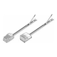
Fixing of the retaining angle
S 401 GB - 11 - 03-06
g
e
(Fig. 19).
fterwards mark the points where the retaining
e
r
oles and affix the retaining
ngles to the ceiling (Fig. 20.1).
ttention: When drilling, cover the drive!
ttachment of the drive head
d shaft
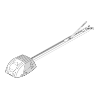
n the collet of the return head (Fig. 20.2).
shown in Fig. 20.3 the drive head has to be
ttached with the 2 Phillips-screws and spring
ashers to the return head.
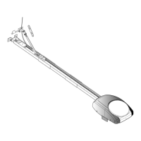
Bring the rail in a level position, fit the retainin
angles to the return head. Make sure, that th
rail is in a level position. The excess lengths of
the angles have to be sawed off
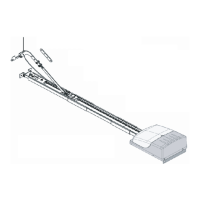
Attachment of the rail
A
angles shall be attached to the ceiling. Mak
sure, that the rail is aligned with the earlie
marked middle of the door.
Drill the required h
a
A
A
The next step is to insert the drive hea
o
As
a
w
Fig. 19
Abb. 20.1-20.3
 Loading...