Ouvert /Ouvert /
Open
FermFermé / /
Closed
TRTR
E2E2
E1E1
C3C3
C3C3C2C2
C1C1
B2B2
C3C3
C2C2
B1B1
C1C1
C3C3
C1C1
C2C2
LEFLEFLEOLEOFCFFCFFCOFCO
1212 1111 1515 1414 96
741010 1313
E1 : Sectionneur + fusible
E2 : Relais thermique
C1 : Contacteur OUVERTURE
C2 : Contacteur FERMETURE
C3 : Contacteur DEFAUT
FCO : Fin de course OUVERTURE
FCF : Fin de course FERMETURE
LEO : Limiteur d'effort OUVERTURE
LEF : Limiteur d'effort FERMETURE
LT : Protection thermique moteur
TR : Transformateur
B1 : Bouton poussoir OUVERTURE
B2 : Bouton poussoir FERMETURE
Légende / Legend
fermé / closed
ouvert / open
CABLAGE CLIENT / CUSTOMER WIRING
OUVERT / OPEN
FERME / CLOSED
Alimentation monophasée /
Single phase power supply
10
11
Condensateur / Capacitor
M
CABLAGE SERVOMOTEUR / ACTUATOR WIRING
1
2
4
3
5
OUVERT / OPEN
6
Résistance de chauffage /
Heating resistance
Contacts fin de course /
Travel limit switches
FERME / CLOSED
Protection thermique moteur
1
12
E1 : Circuit breaker+ fuse
E2 : Thermal relay
C1 : OPENING Contactor
C2 : CLOSING Contactor
C3 : DEFAULT Contactor
FCO : OPEN travel limit switch
FCF : CLOSE travel limit switch
LEO : OPEN torque limit switch
LEF : CLOSE torque limit switch
LT : motor thermal protection
TR : Transformer
B1 : Opening push button
B2 : Closing push button
A
Motor thermal protection
Defaut /Defaut /
Default
Acquittement dAcquittement défaut limiteur d'effort /faut limiteur d'effort /
Torque limit default acknoledgement
ArrArrêt / t / Stop
Arrêt sur limiteur d'effort à
la fermeture : nous consulter./
Stop on torque limit switch in the
closing direction : please consult us.
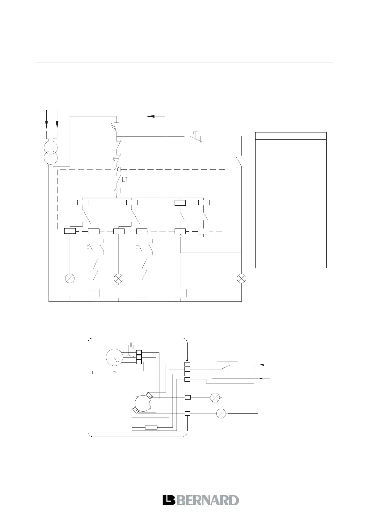
Exemple 1 - Arrêt en position ouverture et fermeture sur contact fin de course avec limiteur d'effort en sécurité
avec réarmement. Schéma valable pour toute la gamme SD sauf OA monophasés pré-câblés (voir exemple 2).
Pour les servomoteurs modèle OA, non équipés de limiteurs d'effort : partie A du schéma seulement./
Example 1 - Stop on travel limit switch on closing and opening directions, torque limit switch in safety action with
manual reset. Diagram valid for the entire SD range excepted the pre-wired one phase OA model (cf. example 2).
For OA actuators, not equipped with torque limit switch : side A of the diagram only.
Servomoteur /
Actuator
EXEMPLES DE REALISATIONS DE COFFRETS DE COMMANDE /
CONTROL PANEL SAMPLE DESIGN
Les servomoteurs sont représentés en position médiane / Actuators are represented in an intermediate position
Exemple 2 - Servomoteurs OA monophasés pré-câblés - Arrêt en position ouverture et fermeture sur fin de course /
Example 2 - Pre-wired one phase OA actuators - Stop on travel limit switch on both opening and closing directions