Do you have a question about the Bernhard Express Dual 3000 and is the answer not in the manual?
Explains the meaning of various symbols and warnings used throughout the manual for safe operation.
Provides essential safety rules, operational limits, and warnings to prevent injury and machine damage.
Instructions on how to safely handle, position, and level the Express Dual machine for optimal operation.
Details on the necessary electrical connections, power specifications, and safety considerations for installation.
Steps for preparing the machine after unpacking, including handle adjustment and shaft lubrication.
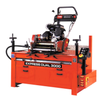
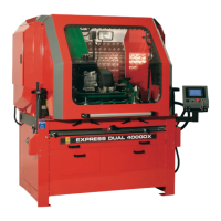
Lists the specific tools and equipment supplied with the Express Dual 3000 and 3000DX models.
Explains the fundamental concepts behind the Express Dual's grinding process and its intended use.
Defines the necessary conditions and checks before operating the machine for reel grinding.
Details the purpose and operation of the machine's motors, traverse, reel drive, grinding wheel, and control buttons.
Steps to prepare the mower unit, including cleaning and ensuring component condition before grinding.
Guidance on correctly positioning and securing the mower unit onto the grinding machine table.
Instructions for configuring the traverse system, including setting travel limits and reversing bars.
Procedure for linking the reel drive unit to the mower's reel shaft for rotation during grinding.
Steps for bringing the grinding wheel into contact with the reel and applying the initial cut.
Details on starting the grinding process, adjusting feed, and using the LED balance system.
Guidance on how to tell when the grinding job is finished and how to safely stop the machine.
A systematic guide to diagnose and resolve electrical faults related to motors, contactors, and control systems.
Step-by-step instructions for safely removing and installing grinding wheels, including dressing.
Recommended lubrication intervals and procedures for various machine components to ensure longevity.
Lists and illustrates the parts that constitute the main structural frame of the Express Dual machine.
Details the components of the mainshaft, its mounting, and the main motor drive system.
Identifies the parts and assembly for the traverse mechanism that moves the grinding wheel.
Lists the components that make up the reel drive system, including motors and flexible shafts.
Details the parts for the control box and the main electrical cabinet, including PCBs and switches.
Lists the components associated with the optional lift table feature for the machine.
Illustrates the electrical connections for the control box, motors, inverter, and power supply.