Do you have a question about the Bernina B 590 and is the answer not in the manual?
General safety guidelines for handling electrical and electronic components.
Caution regarding dangerous voltages present in power connection and components.
Guidelines for protecting electronic components from electrostatic discharge.
List of essential tools and special tool sets for machine maintenance and adjustments.
Instructions for cleaning the machine, including recommended agents and precautions.
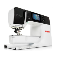
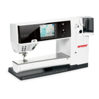
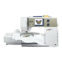
Detailed technical specifications and features for the BERNINA 5 Series models.
Block diagram illustrating the electronic components and their connections.
Description and image of the PCBA-Power component.
General information on the PCBA-CPU-Module, its contents, and replacement procedure.
Overview of the PCBA-Base, its components, internal and external connections.
Layout and components of the PCBA-Front cover and PCBA-Stitching head.
Guidelines for handling electronic components, including ESD precautions and repair.
A flowchart to diagnose and resolve common machine operational issues.
Test for operating voltages on the PCBA-Base using LEDs.
Troubleshooting steps for issues with the upper-thread sensor.
Troubleshooting steps for issues with the lower-thread sensor.
Troubleshooting steps for EEPROM issues causing startup problems.
Troubleshooting steps when the machine fails to start after a repair.
Troubleshooting steps for firmware update failures.
Guidelines and criteria for checking machine settings through sewing tests.
General instructions for removing and refitting machine covers.
Procedures for removing and refitting electronic components and sensors.
Detailed instructions for removing and refitting mechanical components.
Procedure for checking and adjusting belt tensions.
Instructions for adjusting the head-frame plate position in X and Y directions.
Steps for adjusting the height and fixation of the presser foot.
Adjustments related to needle position and distribution.
Procedures for timing hook, needle drive, and feed-dog movements.
Adjustments for the horizontal position and height of the main feed-dog.
Adjustments for the clutch carriage and thread cutter mechanisms.
Procedure for synchronizing the Hall position encoder.
Procedure for adjusting the thread regulator tension and position.
Detailed steps for adjusting upper and lower thread tensions.
Instructions on how to start and exit the Service Program.
Accessing machine basic data, firmware, operating hours, and stitch counts.
Tests related to the machine's display, icons, and touch screen calibration.
Identifying the location of various sensors within the machine.
Tests for checking various signals from machine controls and components.
Identifying the locations of the stepping motors within the machine.
Procedures for various machine adjustments using the Service Program.
Overview of tests related to the embroidery module.
Procedures for performing final machine check-out tests before delivery.
Oiling and lubrication instructions for the modified hook driver.
Step-by-step guide for updating the machine's firmware.
Alternative method for firmware updates if standard method fails.
Procedure after replacing the PCBA-CPU module, including firmware loading.
Explanation of the purpose and benefits of following maintenance guidelines.
Explanation of how stitch and hour counters work and trigger messages.
Table showing maintenance intervals based on stitch and hour counts.
Definition of wear-and-tear parts and their replacement recommendations.
A checklist of maintenance tasks to be performed after service messages appear.
Maintenance checklist specific to the embroidery module.
| Stitch Options | Yes |
|---|---|
| Maximum Stitch Width | 9 mm |
| Stitch Width | 9 mm |
| Embroidery Module | Yes |
| Display | Yes |
| Alphabets | 5 |
| Memory Capacity | Yes |
| Built-in Memory | Yes |
| Needle Positions | 11 |
| Automatic Thread Cutter | Yes |
| Bobbin Winding While Sewing | Yes |
| USB Port | Yes |
| Needle Threader | Automatic |
| Bobbin System | Drop-in Bobbin |
| Type | Computerized Sewing Machine |
| Screen Type | Color Touchscreen |
| Display Type | Touchscreen |
| Weight (kg) | 11.9 |
| Accessories Included | Various presser feet, bobbins, needles, etc. |
| Maximum Sewing Speed | 1000 stitches/min |
| Sewing Speed | 1000 spm |
| Presser Feet | Multiple included |