Be42 OEM's Manual V5.0.XX - December - 2010 page 21
! W A R N I N G ! High voltage is present inside this instrument. To avoid electric-shock hazard,
operating personnel must not remove the protective cover. Do not disconnect the Earth connection. Any
interruption of the grounding connection can create an electric shock hazard. Before making external
connections, always ground the B42 first by connecting the control panel to ground.
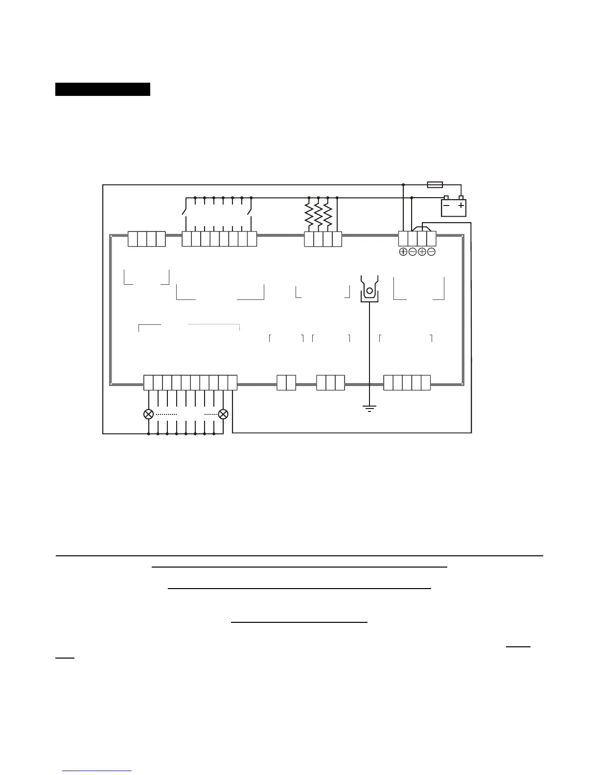
Section13.1 - Be42 Troubleshooting circuit
DIGITAL INPUTS
EMERGENCY STOP
OIL PRESSURE
TEMPERATURE
CONFIGURABLE 1
CONFIGURABLE 2
CONFIGURABLE 3
CONFIGURABLE 4
LOW FUEL
29
30313233
34
35
36
SENSOR INPUTS
OIL-PRESSURE
TEMPERATURE
FUEL-LEVEL
GROUND SENSING
25
262728
SIGNAL-B
GROUND
MODBUS
TERMINATION
SIGNAL-A
40 39 38
37
GENERATOR
INPUT
VL-1
VL-3
15
13
CURRENT
INPUT
C.T. S1
C.T. S2
1211
MAINS INPUT
MAINS VL-1
MAINS VL-2
MAINS VL-3
2018
16
START PILOT
STOP SOLENOID
FUEL SOLENOID
CONFIGURABLE 1
CONFIGURABLE 2
CONFIGURABLE 3
CONFIGURABLE 4
CHARGER ALT.
MAINS CONTACTOR
GENERATOR CONT.
1 2 3 4 5 6 7 8 9 10
OUTPUTS
SUPPLY
23
22 21
12-24V
1A-FUSE
GROUND
BATTERY
BATTERY
RUNNING
RUNNING
Switches
(normally-open)
Not connected
Not connected Not connected Not connected
3 x Resistor 1%
(100-1000Ohm)
3W - LAMP
24
Follow the instructions:
A) - Remove the battery power supply; disconnect all connectors
B) - Push and hold the [ACK-F10] pushbutton, apply the Vdc power supply; all LEDs and Display turn on.
C) - Release the button when you have verified all indicators; the LEDs will turn off and the message [- - - -] will
be displayed.
NOTE - At this stage of the TEST, if the display indicates one of the codes contained in Table13.1 or 13.2,
the Be42 is damaged and should be returned to Bernini Design.
To exit the Troubleshooting, remove the Vdc supply at anytime
13.1 Testing the Pushbuttons
A) - Push the pushbuttons on the front panel one by one. The display will show a message according to Table
13.1. As soon as you release all buttons, the message [- - - -] will be displayed.