17
Rear of the ITR 10
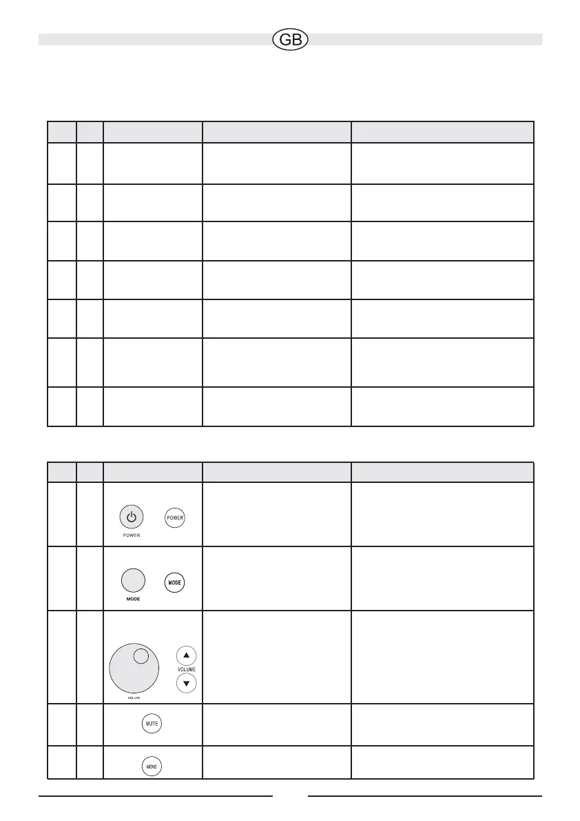
Fig. No. Description Function Notes
1
1
Connection for
the mains cable
12
Mains switch Switches the device
on
Completely separates the
device from the mains supply
FM AERIAL
1
3
AM AERIAL
1
4
Fig. No. Description
Function
Notes
2/4 A/1 Power/Standby
2/4 C/3
2/4 B/2
Mode
Main functions of the ITR 10 (via top panel or remote control)
POWER INPUT
230 V alternating current
S-VIDEO OUT
15
LINE 2 INPUT
16
SUB OUT
17
Mode is displayed on the top
panel LEDs (fig. 2, pos. D)
2/4
44
Mute
Only via remote controlDisconnecting audio
playback
410
Mono
Only via remote controlRadio playback
mono/stereo switch off
Connection of an
FM aerial
Connection of an
AM/MW aerial
Connection of a
TV appliance
Connection of another
audio source
Connection of a
subwoofer
75 Ohm, required for
reception
300 Ohm
Transfers the image from
a video iPod to a TV
RCA phono socket for
connecting a CD player or
similar device
Bass output for subwoofers
with RCA phono input
Volume control
Adjusting the volume
Selection between
playback from radio,
iPod or 2 other audio
sources
Switching from
Standby to ON or
from ON to Standby
Connections and functions of the ITR 10