12
/ Wiring diagram
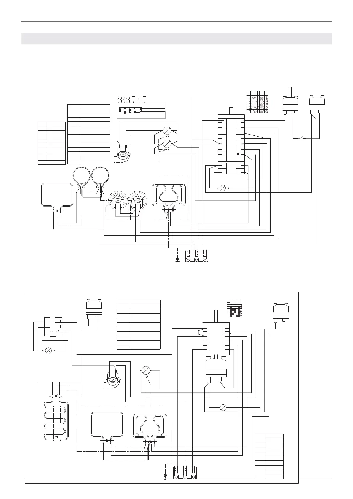
WIRING DIAGRAM
The electric wiring diagrams and schematics are attached behind the range, and should not be removed
except by a service technician, then replaced after service.
DFM
n
S
LF
MVT
RG+RC
RP
m
a
b
M
L1 N L2
GROUND
TSS
1
2
Simb. Description
mBrown
rRed
gv Green
vViolet
gr Grey
aOrange
nBlack
bBlue
bi White
COLOURS
Simb. Description
C+T Switch + thermostat
GE Griddle Thermostat
LF Oven lamp
MTerminal Block
MVT Cooling fan motor
RC+RG Upper/grill element
RGR Griddle Element
RP Lower element
S Signal lights
TSS Safety Thermostat
LEGENDA
P1
P3
P2
5
2
1
3
4
COM
T
2
P1-2
P1-1
P1-3
5
3
4
0
1
P3-5
P2-4
RGR
TSS
1
2
S
GE
bi
bi
r
n
m
bi
a
a
bi
n
b
r
a
a
bi
v
g
a
b
b
48 RIGHT SIDE
G
IGN
bi
S
LF
MVT
T
RG+RC
RP
n
a
b
b
M
L1 N L2
GROUND
TSS
1
2
CMV
P1
Commutatore.9+0
1
P2
P3
P4
P5
P6
P7
P8
P1
P2
2
3
4
5
6
7
8
1
2
P2
P1
P8
P7
P6
P5
P4
P3
P2
1
0
4
3
P1
2
5
6
7
8
9
COM
RCRC
MV MV
LF
Simb. Description
mBrown
rRed
gv Green
vViolet
gr Grey
a Orange
nBlack
bBlue
bi White
COLOURS
Simb. Description
IGN Ignition Micro switches
COM Oven Function Selector
CMV Cooling fan air sensor switch
LF Oven lamp
M Terminal Block
MV Fan motor
MVT Cooling fan motor
RC Round element
RC+RG Upper/grill element
RP Lower element
S Signal lights
TSS Safety Thermostat
T Thermostat
LEGENDA
v
v
n
bi
bi
a
a
b
r
a
gr
b
v
b
a
bi
r