BESTip ATA 20L User Manual
7
This manual gives you easy-to-follow instructions for installing
and using the BESTip ATA 20L.
For further details on these applications, please refer to
www.iptelcom.com.tw
Physical Description
This section provides physical description of BESTip ATA 20L.
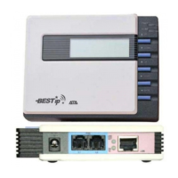
Front Panel
There are five buttons on the front panel for quick and easy
configuration.
UP Button
NEXT Button
BACK Button
OK Button
DOWN Button
Green LED
Power Si
BESTip ATA 20L User Manual
8
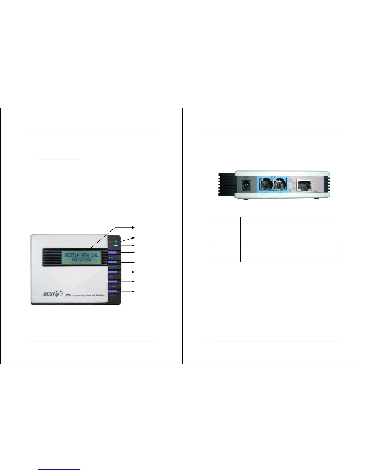
Rear Panel
There are four connectors on the rear panel to connect to the
related devices. The description is listed below (left to right).
DC 12V
DC Adapter Connector: connects to the 12V DC
power adapter.
L1
RJ-11 Connector: FXS interface is for connecting
to the analog phone sets or C.O. port of PBX.
L2
RJ-11 Connector: FXS interface is for connecting
to the analog phone sets or C.O. port of PBX.
LAN RJ-45 Connector: cables to your IP network.
Power L1 L2 LAN