english
1716
OPERATING INSTRUCTIONS
DT 250 / DT 252 / DT 280 / DT 290 / DT 291 /
DT 287 / DT 297
Thank you for selecting one of the DT 200 series professional studio
headphones or headsets. They have been made in Germany from high-
grade materials and assembled under stringent quality and performance
tests to provide you with a professional communications tool. Please
take some time to read through this instruction booklet to give you an
idea of the design criterion and some information on connection, use
and maintenance.
Design Features
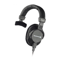
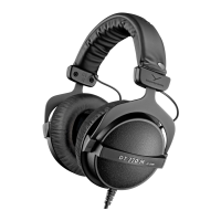
DT 250 / DT 252
The DT 250 / DT 252 is a closed dynamic headphone offering
excellent ambient noise isolation making it suitable for all kinds of
applica tions in broadcasting and recording studios. The headband
and earphone cushioning systems have been carefully designed for
maximum comfort and unobtrusive style. The powerful neodymium
magnet system provides high-fidelity reproduction and a balanced
sound. The standard impedance is 80 Ω. Furthermore, versions with
250 Ω systems are available. The connecting cables to the ear
monitors run safely in the headband and the main connecting cable
is terminated on one side with a multi-pin connector.
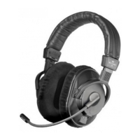
DT 280 / DT 290
Same as DT 250, but featuring the dynamic hypercardioid DM 290
microphone. The DT 280/DT 290 headset is used in intercom and
talkback systems as well as other applications where a dynamic micro-
phone is required. The DT 280/DT 290 V.11 has an integrated micro-
phone preamp for AB-powering.
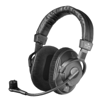
DT 291 / DT 297
Same as DT 250, but featuring an omnidirectional electret condenser
microphone (DT 291) or a cardioid condenser microphone (DT 297). The
DT 291 PV / DT 297 PV is equipped with an integrated preamp for
phantom powering.
The DT 297 V.11 has an integrated microphone preamp for AB-powering.
Connection
The DT 250 / DT 252 headphones are supplied with an appropriate
connecting cable. The the DT 280 / DT 290 / DT 291 / DT 287 / DT 297
headsets are supplied without connecting cable. For appropriate
connecting cables, please refer to “Optional Accessories”. Direct
solder connections can be made to all cables with free ends (for cable
connection refer to ”Block Diagram”). Upon request the required
plugs can be connected at the factory.
It is important that the external equipment the studio headphones or
the headsets will be connected to are of good quality and of the
correct impedance and power ratings to get the best performance
from them. Please refer to the ”Technical Specifications” for detailed
information.
The microphone of the DT 280 / DT 290 headset is designed for
balanced connection. But it can be also connected to unbalanced
microphone inputs.
The DT 291 PV or DT 297 PV headsets are suitable for the connection
to balanced microphone inputs with phantom power. At a distance
of 5 cm the microphone level is 13 mV or 250 mV.
Use the DT 280/DT 290 V.11 or DT 287/DT 297 V.11 headset with
integrated preamp for connecting to TV cameras with a microphone
input for AB-powering. At a distance of 5 cm the microphone level
can be adjusted between 52 mV and 1.3 V at normal speech volumes.
The supply voltage for the pre-amplifier can vary between 6 - 27 V. The
power consumption is at:
DT 290 V.11 DT 297 V.11
6V R
vor
330 Ω 8mA 6mA
12 V R
vor
330 Ω 23 mA 20 mA
20 V R
vor
330 Ω 43 mA 40 mA
27 V R
vor
330 Ω 61 mA 57 mA
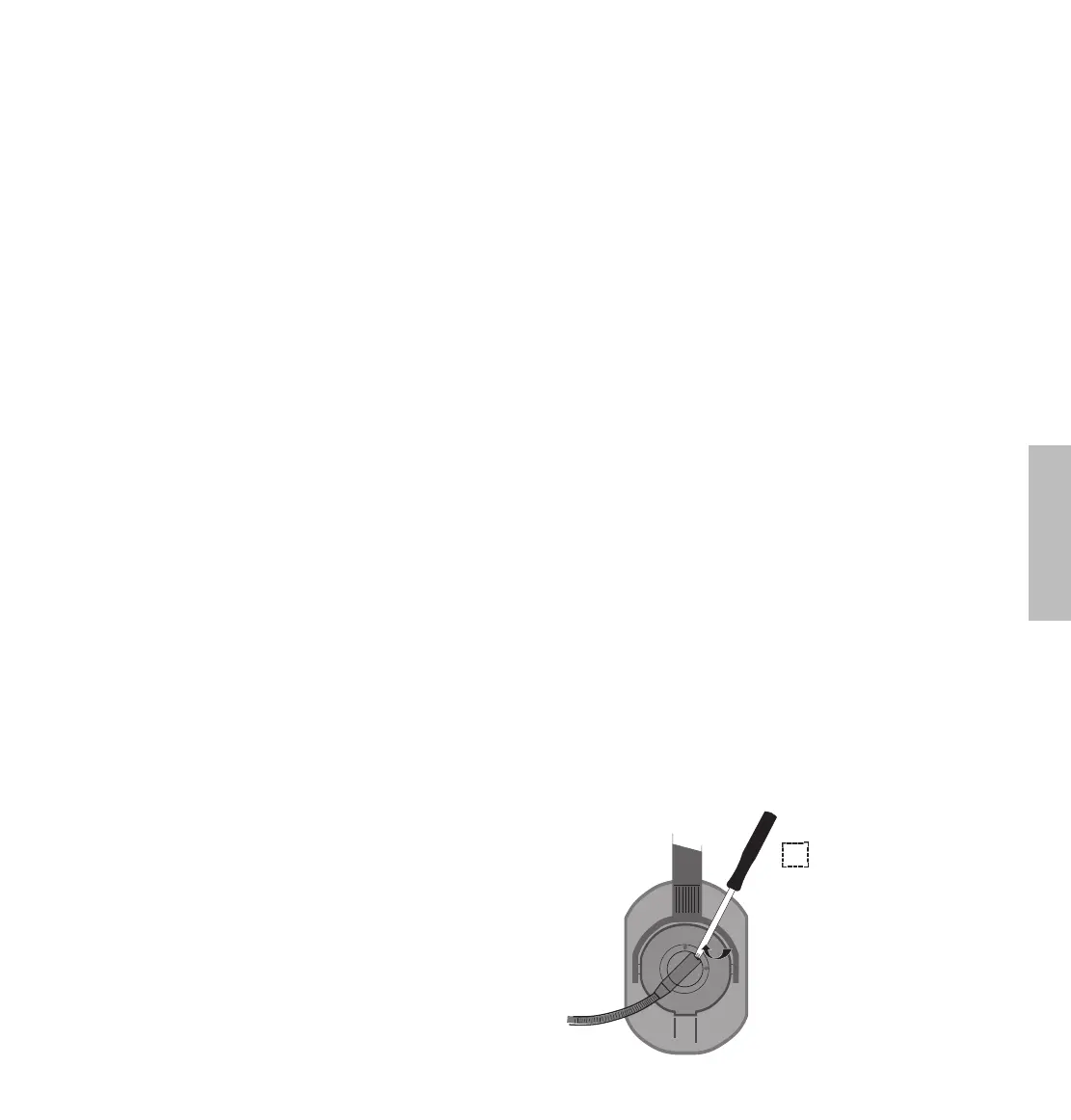
Operation
The head phones are fully adjustable and should be positioned for the
best fit over the ears. This will give maximum long-term comfort and
will minimise sound leakage or spill. Convention states that the boom
microphone is placed over the left ear. The microphone can be used
from the right ear, but if true L and R headphone status needs to be
maintained, it will be necessary to make a custom lead with the head-
phone connections reversed (swap brown/orange on the left side and
red/blue on the right side). For con nections refer to ”Block Diagram”.