Do you have a question about the BFI Automation 3001S and is the answer not in the manual?
The BFI Automation 3001S is a flame amplifier designed for the safe and efficient operation of flame monitoring systems in industrial applications. It evaluates flame scanner pulses to activate a flame relay upon detecting an adequate flame signal. The device incorporates a fail-safe self-monitoring system and is approved for continuous operation in accordance with European standards EN 298:2012-11, ensuring that any component failure leads to a safe switch-OFF of the flame relay.
The flame amplifier processes signals from a flame scanner, which are received as pulse telegrams through a filter and pulse shaper stage. These signals are then distributed to three distinct function channels:
The flame amplifier features two independent monitoring levels (Time I and Time II), which can be externally selected. Each level has its own sensitivity setting and switch-OFF time, allowing for fuel or load-related optimization of flame monitoring. The device also supports the parallel or alternating connection of a second flame scanner. The flame relay (K101) is energized only when both the RM and RF channels are simultaneously switched on.
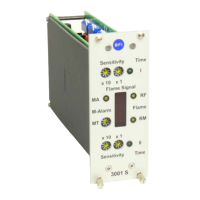
A pre-alarm warning function is included to indicate unfavorable combustion processes before a complete system switch-OFF. This warning, adjustable in 10% steps of the flame signal via rotary switch MT, helps detect continuous degradation of the flame signal due to factors like soiling of the flame scanner lens, changes in flame/fuel quality, or flame raising, thereby improving plant availability. The MA LED serves as an indicator, and a 24 V / 100 mA output is available for external processing of this warning.
The 3001S is designed for use in 19" standard card magazines (DIN 41494). It offers flexible installation options, including 19"-built-in housing (rack mount) and 19"-built-on housing (wall mount), with various sizes available to accommodate different numbers of slide-in modules.
Connection possibilities include pin connectors (Flat-Pin 2.8 mm, Maxi-Termipoint, wire wrap). The device requires a 24 VDC supply voltage, which must match the type plate indication. All installation and connection work must be performed by qualified and approved specialist staff, adhering to legal stipulations and plant operator instructions.
For initial operation, it's crucial to check and adjust switch-ON times and other parameters. The flame intensity indicator should ideally be between 50% and 100% for stable monitoring. The flame amplifier is factory-set with maximum sensitivity (99), safety switch-OFF times of 1 second, a switch-ON threshold of 25%, and a pre-alarm warning at 40%. The analogue output is factory-set to 0-20 mA.
The variable switch-ON threshold (hysteresis) can be set between 25% and 75% to block out light from neighboring burners, though continuous signals from such flames exceeding 25% are a safety risk and should not be ignored. After changing the switch-ON threshold, the burner must be stopped to verify that the switch-OFF threshold is safely met and the flame relay switches off.
Two independently set switch-OFF times can be switched over by an external 24 VDC signal applied to pin a16. The shorter switch-OFF time should be allocated to channel 1 (Time 1) to ensure safety in case of signal loss. Changes to switch-OFF times require the acceptance of an approval expert.
The potential-free relay contact for "Flame on / off" is internally protected by a T1 amp fuse, which is accessible for replacement when the device is unplugged. A short-circuit-proof output on pin c16 provides the pre-alarm warning signal.
The flame amplifier is designed to be maintenance-free. For cleaning, only a moist cloth should be used to wipe the front panel from the outside. Regular checks for external damage and defects are recommended, and any issues should be reported and corrected immediately. Maintenance and repair work must be carried out by authorized specialist staff, following all safety instructions and deadlines stipulated by BFI Automation. This includes observing electrical regulations, tightening loosened screw connections, remounting and checking safety devices after repairs, and disposing of materials safely. The use of original spare parts and accessories is mandatory to maintain warranty validity and safety. It is recommended that operators consider a service contract with BFI Automation for regular checks and timely availability of parts.
| Brand | BFI Automation |
|---|---|
| Model | 3001S |
| Category | Amplifier |
| Language | English |