Do you have a question about the BFI Automation 3001D and is the answer not in the manual?
Provides an overview of the operating instructions' purpose and applicability.
Explains the meaning of different warning symbols used in the manual.
Outlines copyright rules and restrictions for using the documentation.
Details the warranty conditions and exclusions for the flame amplifier.
Specifies the responsibilities of the operating company for safe device operation.
States the limitations of liability for the manufacturer regarding device use and errors.
Lists EU directives and standards the system complies with.
Provides contact details for the manufacturer, BFI Automation.
Defines the specific applications for which the flame amplifier is designed.
Specifies qualifications and conditions for personnel working with the device.
General safety guidelines to prevent accidents and hazards during operation.
General principles for ensuring safety equipment is functional and enabled.
Lists the specific safety devices integrated into the flame amplifier.
General safety principles for performing maintenance and troubleshooting tasks.
Specific safety rules for working with electrical and electronic components.
Guidelines for testing devices according to German workplace safety regulations.
Procedures for ensuring safe and correct operation through testing.
Highlights the main characteristics and approvals of the flame amplifier.
Provides technical specifications for electrical, mechanical, and functional aspects.
Specifies the weight of the flame amplifier.
Details the physical dimensions of the flame amplifier.
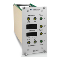
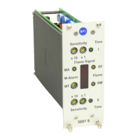
Describes the front panel controls and indicators for adjustment and display.
Explains the internal design and operating principle of the flame amplifier.
Presents a block diagram illustrating the functional connections within the device.
Lists the items included in the standard delivery package.
Describes the packaging materials and disposal considerations.
Provides instructions for handling the device during transport.
States the weight of the flame amplifier.
Details the physical space required for installation, including dimensions.
Guide for mounting the device in a 19-inch rack.
Guide for mounting the device in a wall-mounted housing.
Provides dimensions for different 19" housing configurations.
Details on making the electrical connections, including safety warnings.
Shows the terminal layout and function for wiring the device.
Guidelines for proper storage conditions to maintain device integrity.
Describes the analogue and digital measurement channels and their functions.
Explains the role and operation of the monitor channel for system self-tests.
Describes the evaluation channel and its role in flame signal processing.
Details how to set the variable switch-ON threshold for the evaluation channel.
Specifies the fixed switch-OFF threshold for the device channels.
Explains the pre-alarm warning function for indicating combustion issues.
Describes how to set and the importance of safety switch-OFF times.
Details the available signal outputs for monitoring and external processing.
Explains the adjustable impulse divider for signal reduction.
Instructions for connecting multiple flame scanners in parallel.
Instructions for connecting the flame amplifier to other system components.
Procedures for testing the flame amplifier to ensure correct operation.
Steps for the initial start-up and operation of the device.
Details the default factory settings for various parameters.
Guide to configuring DIP switches and other settings for operation.
| Brand | BFI Automation |
|---|---|
| Model | 3001D |
| Category | Amplifier |
| Language | English |