technology for your future
Automation
BFI
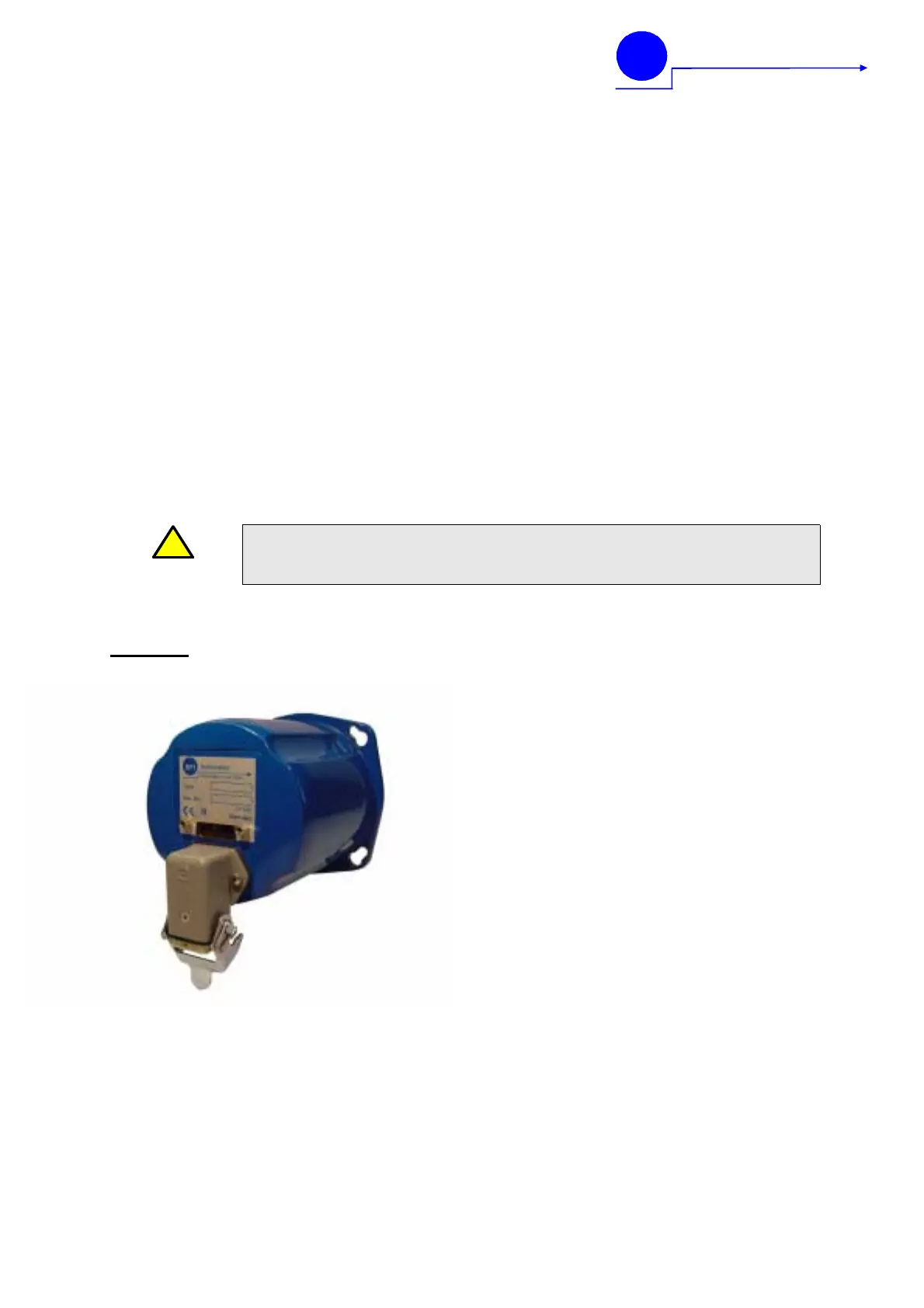
Compact Flame Controller
CFC 2000
UV, UV1, IR, IR1, IR2
- Flame scanner with integrated flame amplifier and flame relay.
- TÜV approved, DIN-DVGW, DIN-CERTCO certified
- For intermitted, continuous operation and 72-hours operation
- Type UV, UV1 : For natural Gas-, Oil- and dual fuel operation
- Type IR (VIS-IR): For monitoring of oil flames on diffusion burners
- Type IR1 (IR): For monitoring of natural gas flame in duct burners
- Type IR2 (IR): in preparation
- Dual channel flame monitoring and evaluation system.
- Adjustable sensitivity for both channels separate by software.
- Analogue output 0(4) – 20mA Intensity
- Possible flame evaluation by software
- Status indication of flame relay, and intensity indication by LED
- No additional wiring to separate flame scanners.
- Class of protection IP 65.
!
WARNING
WARNING: IMPROPER INSTALLATION OF THESE PRODUCTS
MAY BE HAZARDOUS TO LIFE AND PROPERTY
Function
For the flame radiation analysis, a well approved
integral procedure in the respective spectrum is
carried out with the compact flame controller.
After a pre-amplification, the unwanted CW light
component is withdrawn from the output signal of
the wear-resistant detector. The subsequent
sensitiveness attitude allows an attenuation of
the signal for adaptation to the combustion proc-
ess. The post-connected band pass filter caused,
that only the typical modulation of the flame ra-
diation of the primary combustion zone is valued
and so extraneous light signals by neighbour
burners can be distinguished from the own fla-
me.
Further functional groups include signal condi-
tioning and other for the so-called dynamic
monitoring channel which checks the fail safe
function of the device continuously.
A component or component defect leads to an
immediate disconnection of the flame relay,
which one is available as a floating change-over
contact for use with the burner management sys-
tem.
The switching condition is announced addition-
ally by a yellow LED on the reverse side of the
device behind the Perspex pane.
For the optimal adjustment of the compact flame
controller the flame strength can be read off di-
rectly on the device by means of a pulsating
green LED. For the visualization or remote indi-
cation, a current output is available at 0 or 4-20
mA.
The safety switched-off time which depends on
the combustibles to be checked is set ex-works
to a second. Longer switched-off times are op-
tionally available upon request.
 Loading...