technology for your future
Automation
BFI
Installation
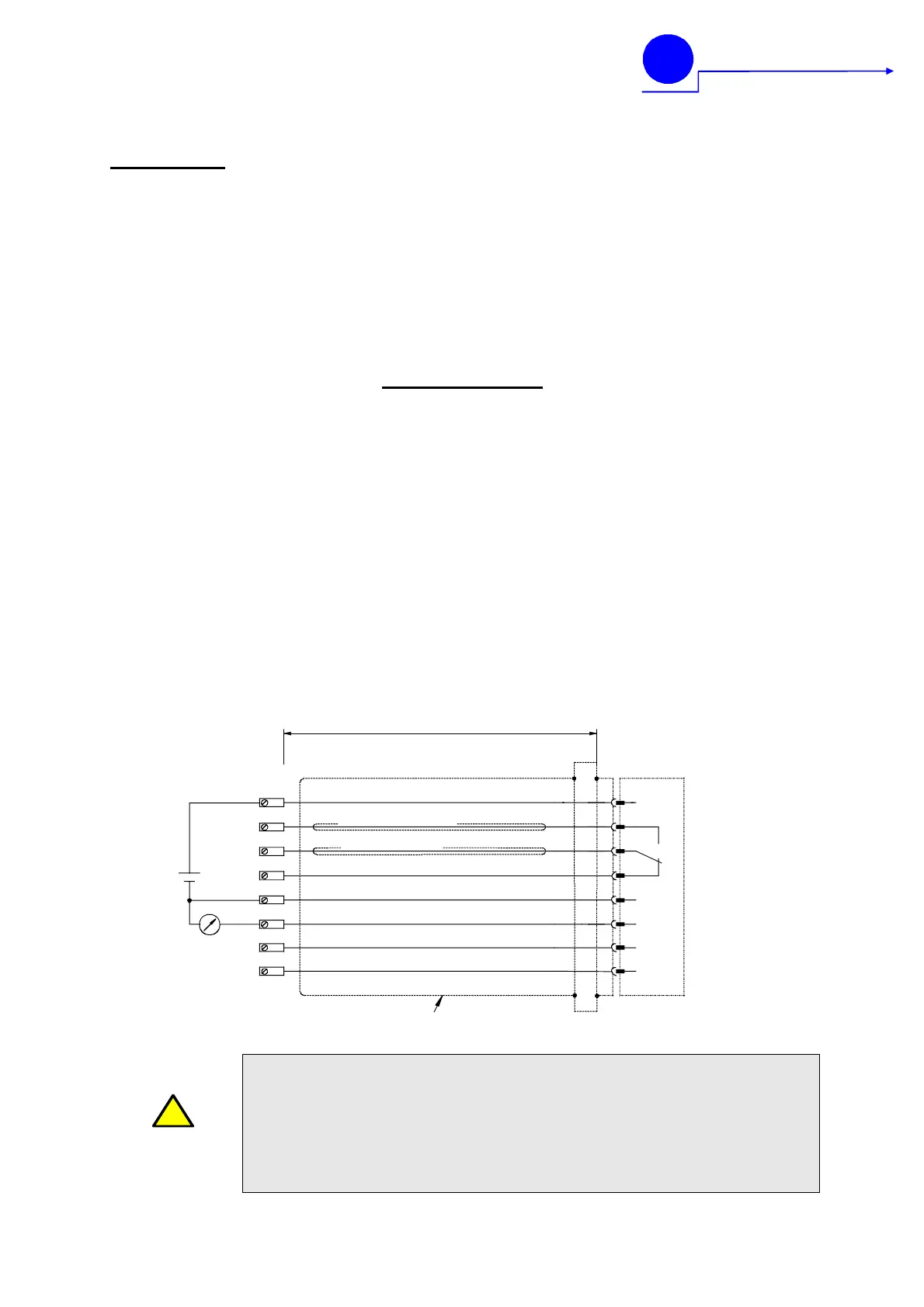
The pin assignment of the connector is shown in
the wiring diagram.
The output signal 0(4)-20mA for flame intensity is
not separated by the supply voltage, so the sig-
nal refers to the operating voltage measures. If
this should lead to problems, a corresponding
isolating transformer can be provided upon re-
quest. The burden of 250 ohms should always
not be exceeded.
The device is immediately ready for operation af-
ter switch-on of the supply voltage.
Wiring Diagram
Pin/Terminal Description colour code
BFI special cable KW6
1 Flame relay: Root white
2 Flame relay: Contact flame ON brown
3 Flame relay: Contact flame OFF pink
4 power supply: +24 V DC green
5 power supply: 0V (GND) yellow
6 current output 0(4)-20 mA grey
7 switch over canal 1 / canal 2 – 24V DC red
8 failure indication output +24V DC blue
!
CAUTION
CAUTION: In order to guarantee a proper operation the compact
flame controller must be tested several times at all conditions. The
burner has to be started and stopped several times (the flame relay
must always interrupt reliably with no flame on). Carry out these tests
while different neighbour burners are started and stopped as well as
on different boiler loads. This is a vital assumption for a proper and
reliable operation.
sensitivity switch over time I / II
7
red
7
failure indication output
8
blue
8
power supply +24V DC
flame relay "flame ON"
flame relay "root"
flame relay "flame OFF"
outer braided shield
current output 0/4 - 20mA
4
2
1
3
4
2
6
green
brown
white
pink
grey
CFC
2000
6
power supply 0V (GND)
5
yellow
5
1
3
BFI-special cable KW5

 Loading...