Do you have a question about the BFI Automation CFC 3000L and is the answer not in the manual?
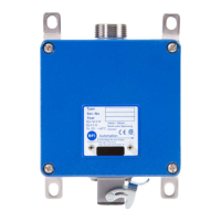
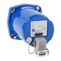
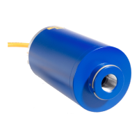
The BFI Automation Compact Flame Controller CFC 3000L is a device designed for the monitoring of flames in industrial steam generators, single and multi-burner furnaces. It is intended for selective and continuous burner monitoring. The CFC 3000L must only be operated with fiber optic cables supplied by BFI Automation.
The CFC 3000L analyzes flame radiation using an integral method within a specific spectral range. After pre-amplification, unmodulated light is removed from the detector's output signal. A sensitivity setting allows signal attenuation to adapt to firing conditions. A downstream bandpass filter ensures that only the typical flame radiation modulation from the primary combustion zone is evaluated, enabling the device to distinguish the monitored flame from extraneous light sources from neighboring burners.
The device incorporates a dynamic monitor channel that continuously monitors its fault-free state. Any component defect immediately triggers a switch-OFF of the flame relay, which is a floating changeover contact for processing in the burner controller. The switching status is also indicated by a yellow LED on the rear panel. For optimal adjustment, flame intensity can be read directly from a pulsating green LED on the device. A 0(4) to 20 mA current output is available for visualization or remote display. The safety switch-OFF time, which depends on the fuels being monitored, is factory-set to 1 second, but longer switch-OFF times can be configured if required.
The CFC 3000L offers various spectral sensitivities:
The angle of view is 3°. The device features fully electronic self-monitoring, performed once every 800ms. Operating voltage is 24V DC ± 15%, with an approximate current consumption of 200mA. It uses a max. 1A slow pre-fuse and is designed in accordance with protection class III SELV. Operating temperature ranges from -20°C to +70°C for the standard version, and -55°C to +85°C for UV/UV1 types. The current output is 0(4) to 20mA (Ra<250Ω), with a software-variable current window. A fault output provides 24V DC, short circuit-proof. Range changeover is externally selected via a 24V DC signal. The flame relay has 1 changeover contact, floating, with optional wire break detection. It supports a maximum switching voltage of 48V, a maximum switching current of 1A (fused with 0.5A), and a maximum switching power of 30W. Switching thresholds are programmable by software. The safety switch-off time is adjustable from 0.4 to 5 seconds, factory-set to 1 second. The fiber optic connection uses an M30 outer thread, metric.
The CFC 3000L features a four-step frequency filter in the signal input, allowing extraneous light to be filtered out before software evaluation. The limit frequencies of the high-pass filter can be set to 30, 60, 90, or 120 Hz using dip switches. These settings should only be changed if software adjustment is not possible. The safety switch-OFF time of the safety channel (hardware) is set via jumpers to 1, 3, or 5 seconds. If a 2-second switch-OFF time is needed, the jumper must be in position 2 (3 seconds), and the evaluation channel's switch-OFF time set to 2 seconds via software. The shorter of the two channels' switch-OFF times always takes priority. For selective burner monitoring, the device must be installed so that the primary combustion zone in all load ranges is within its visual angle. The sighting axis should intersect the first third of the flame of its own burner and not intersect the first third of other burners' flames. An optical adjustment aid is recommended for precise alignment. The device can be connected to a converter box 5012 (optional) which provides power, a secondary relay for higher loads (up to 250V AC, 1A), and an additional 0(4) – 20mA current output for flame flicker frequency. The converter box also allows for serial RS232 signal transmission and visualization of data on a connected computer via USB. Up to 64 CFC 3000 units can be connected in a single loop and monitored in parallel using special visualization software.
The compact flame controller is maintenance-free. For cleaning, only a moist cloth should be used to wipe the exterior housing. When storing the device, ensure the fiber optic connector socket is covered with a suitable cap. For SIL applications, maintenance should follow the guidelines in the SIL-Safety Handbook SIL-HB_CFCx000. Regular checks for defects are crucial, and any faults must be corrected immediately. Work on electrical components should only be performed by authorized electrical specialists after disconnecting the device from the mains power supply. If working on live parts, a second person should be present to disconnect power in an emergency, and only insulated tools should be used. After maintenance or repair, all safety devices must be reinstalled and electrical/mechanical checks performed. The operating company is responsible for ensuring the device is operated in proper condition and that all safety requirements are met.
| Brand | BFI Automation |
|---|---|
| Model | CFC 3000L |
| Category | Controller |
| Language | English |