EasyManua.ls Logo

BFT ALCOR N User Manual

BFT ALCOR N
11 pages
To Next Page IconTo Next Page
Page #1 background imageLoading...
Page #1 background image
D811509_02 04/06/07
ISTRUZIONI D'USO E DI INSTALLAZIONE
INSTALLATION AND USER'S MANUAL
INSTRUCTIONS D'UTILISATION ET D'INSTALLATION
MONTAGE- und BEDIENUNGSANLEITUNG
INSTRUCCIONES DE USO Y DE INSTALACION
INSTRUÇÕES DE USO E DE INSTALAÇÃO
I
GB
F
D
E
P
QUADRO COMANDO
CONTROL PANEL
CENTRALE DE COMMANDE
STEUERPLATINE
CUADRO DE MANDOS
QUADRO DE COMANDO
Via Lago di Vico, 44
36015 Schio (VI)
Tel.naz. 0445 696511
Tel.int. +39 0445 696533
Fax 0445 696522
Internet: www.bft.it
E-mail: sales@bft.it
ALCOR N
8
027908 2 9 7 0 6 8
9
10
11
12
13
14
15
16
17
18
19
20
1
2
3
4
5
6
7
8

Other manuals for BFT ALCOR N

Question and Answer IconNeed help?

Do you have a question about the BFT ALCOR N and is the answer not in the manual?

BFT ALCOR N Specifications

General IconGeneral
ManufacturerBFT
TypeControl Panel
Power supply230 V
Power input230 V AC
Maximum Current Consumption500 mA
Number of programmable outputs2
Number of Outputs4
Output TypeRelay
Operating temperature-10°C to +55°C
Weight1.2 kg
Operating Voltage24 V

Summary

INSTALLATION AND USER'S MANUAL

DECLARATION OF CONFORMITY

GENERAL PRODUCT INFORMATION AND SAFETY

ESSENTIAL SAFETY WARNINGS

Crucial safety precautions for installation, operation, and user responsibilities.

INSTALLATION GUIDELINES AND TECHNICAL SPECIFICATIONS

GENERAL SAFETY FOR INSTALLATION

Detailed safety requirements and warnings for the installation process.

TERMINAL BOARD CONNECTIONS

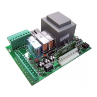
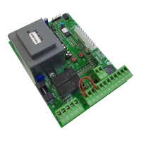
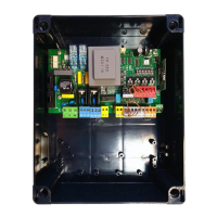
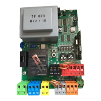
Comprehensive guide to wiring connections for the ALCOR N control unit.

CONFIGURATION AND PROGRAMMING OPTIONS

DIP-SWITCH CONFIGURATION

Guide to configuring the control unit's functions using DIP switches.

TRANSMITTER PROGRAMMING AND MEMORY MANAGEMENT

Procedures for programming, cloning, and managing radio transmitters and receiver memory.

ADVANCED FEATURES AND ACCESSORIES

RADIO TRANSMITTER CLONING AND PROGRAMMING

Details on cloning transmitters and advanced programming for collective receivers.

INSTALLATION DIAGRAMS

TERMINAL WIRING DIAGRAM

Detailed wiring diagram illustrating connections to the control unit's terminal block.

PROGRAMMING DEVICE CONNECTIONS

Related product manuals