1) GENERALITÁ
Fotocellula Mod. Cellula FLX per applicazione esterna, costituita da una coppia
trasmittente ricevente con lampeggiante integrato.
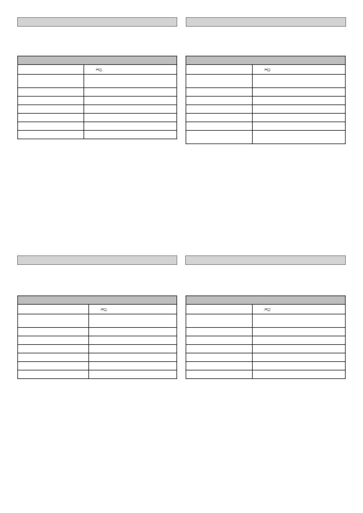
2) DATI TECNICI
CELLULA FLX
Tensione di alimentazione
24 V
Corrente Assorbita
TX: 65mA
RX: 70mA
Portata contatti 30V, 1A
Grado di protezione IP45
Temperatura di esercizio -20/+55°C
Portata max. 15 m (ridotta in caso di nebbia-pioggia)
Dimensioni 130x45x35 (HxLxD)
Categoria secondo la EN954-1 Cat 2
3) CORRETTO ALLINEAMENTO Fig. A
4) CORRETTO ALLINEAMENTO DI DUE COPPIE DI FOTOCELLULE Fig. B
5) FORATURA PER INSTALLAZIONE Fig. C
6) INSTALLAZIONE Fig. D
7) COLLEGAMENTI Fig. E
8) CORRETTO ALLINEAMENTO Fig. F
Al termine del collaudo, eseguire alcune manovre di prova e vericare che,
quando si interrompe il fascio interponendo un ostacolo, l’automazione reagi-
sca correttamente.
1) GENERAL INFORMATION
Cellula FLX photocell for external application, comprising a transmitter-receiver
pair with built-in ashing light.
2) SPECIFICATIONS
CELLULA FLX
Supply voltage
24 V
Current demand
TX: 65mA
RX: 70mA
Contact capacity 30V, 1A
Protection rating IP45
Operating temperature range -20/+55°C
Max range 15 m (reduced in case of fog/rain)
Operating range 130x45x35 (HxLxD)
Category according to EN 954-1 Cat 2
3) CORRECT ALIGNMENT Fig. A
4) CORRECT ALIGNMENT OF TWO PAIRS OF PHOTOCELLS Fig. B
5) HOLES FOR INSTALLATION Fig. C
6) ASSEMBLING Fig. D
7) WIRING Fig. E
8) CORRECT ALIGNMENT Fig. F
Once inspection is complete, perform a few test cycles and check that the au-
tomated system reacts as it should when the beam is broken by placing an ob-
stacle in the way.
1) ALLGEMEINES
Fotozelle Modell Cellula FLX für Anwendungen im Außenbereich, bestehend
aus einem Sender- und Empfängerpaar mit integrierter Blinkleuchte.
2) TECHNISCHE DATEN
CELLULA FLX
Versorgungsspannung
24 V
Stromaufnahme
TX: 65mA
RX: 70mA
Kontaktleistung 30V, 1A
Schutzgrad IP45
Betriebstemperatur -20/+55°C
Max. Reichweite 15 m (geringer im Falle von Nebel/Regen)
Abmessungen 130x45x35 (HxLxT)
Klassizierung nach EN954-1 Kategorie 2
3) KORREKTE POSITIONIERUNG DER LICHTSCHRANKE Abb. A
4)
KORREKTE POSITIONIERUNG VON ZWEI LICHTSCHRANKEN-PAAREN Abb. B
5) LOCHÖFFNUNGEN FÜR DIE INSTALLATION Abb. C
6) INSTALLATION Fig. D
7) ELEKTRISCHER ANSCHLUSS Abb. E
8) KORREKTE AUSRICHTUNG Abb. F
Zum Abschluss der Funktionsprüfung betätigen Sie bitte mehrfach die Anlage,
um zu überprüfen, ob der Automatikantrieb fehlerfrei reagiert, wenn ein Hin-
dernis von der Lichtschranke erfasst wird.
1) GÉNÉRALITÉS
Photocellule Mod. Cellula FLX pour application extérieure, formée par une paire
d’émetteur-récepteur avec clignotant intégré.
2) ONNÉES TECHNIQUES
CELLULA FLX
Tension d’alimentation
24 V
Courant Absorbé
TX: 65mA
RX: 70mA
Portée contacts 30V, 1A
Degré de protection IP45
Température de service -20/+55°C
Portée maxi
15 m (réduite en cas de brouillard ou de pluie)
Dimensions 130x45x35 (HxLxD)
Catégorie conformément à
EN954-1
Cat 2
3) LIGNEMENT CORRECT Fig. A
4) ALIGNEMENT CORRECT DE DEUX PAIRES DE PHOTOCELLULES Fig. B
5) PERCEMENT POUR INSTALLATION Fig. C
6) INSTALLATION Fig. D
7) CONNEXIONS Fig. E
8) ALIGNEMENT CORRECT Fig. F
A la n de l’essai, faites quelques manœuvres d’essai et vériez si l’automatisa-
tion réagit lorsque le faisceau est interrompu par un obstacle.
MANUALE PER L’INSTALLAZIONE
INSTALLATION MANUAL
MANUEL D’INSTALLATION
MONTAGEANLEITUNG
8 - CELLULA FLX
D811764_02
 Loading...