ENGLISH
INSTALLATION MANUAL
1) GENERAL INFORMATION
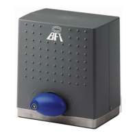
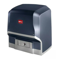
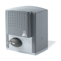
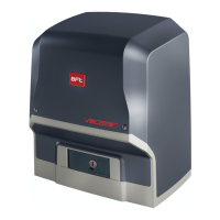
The DEIMOS BT A actuator is highly versatile in terms of installation options due
to the extremely low position of the pinion, the actuator’s compact nature and the
height and depth adjustment features it oers. The adjustable electronic torque
limiter provides anti-crush safety. Manual emergency operation is extremely easy
to perform using just a release lever.
Stopping at end of travel is controlled by electromechanical microswitches.
The HAMAL control panel comes with standard factory settings.
Any change must be set by means of the TRIMMER and DIP SWITCH settings.
Its main features are:
- Control of 1 low-voltage motor
- Obstacle detection
- Separate inputs for safety devices
- Built-in radio receiver rolling code with transmitter cloning.
The board has a terminal strip of the removable kind to make maintenance
or replacement easier. It comes with a series of prewired jumpers to make the
installer’s job on site easier. The jumpers concern terminals: 70-71, 70-72, 70-74.
If the above-mentioned terminals are being used, remove the relevant jumpers.
TESTING
The HAMAL panel controls (checks) the start relays and safety devices (photocells)
before performing each opening and closing cycle.
If there is a malfunction, make sure that the connected devices are working
properly and check the wiring.
2) TECHNICAL SPECIFICATIONS
MOTOR
400 600
Power supply
110-120V 50/60Hz
220-230V 50/60 Hz(*)
110-120V 50/60Hz
220-230V 50/60 Hz(*)
Motor 24V
24V
Power input 50W 70W
Max. current demand
0,5A (230V
~
) - 1A
(110V
~
)
0,5A (230V
~
) - 1A
(110V
~
)
Pinion module (standard) 4mm (14 teeth) 4mm (14 teeth)
Leaf speed (standard) 12m/min 12m/min
Max. leaf weight - standard** 4000N (≈400kg) 6000N (≈600kg)
Pinion module (fast) 4mm (18 teeth) 4mm (18 teeth)
Leaf speed (fast) 15.5m/min 15.5m/min
Max. leaf weight - fast** 3000N (≈300kg) 3600N (≈360kg)
Max. torque 20Nm 30Nm
Impact reaction
Electronic torque
limiter
Electronic torque
limiter
Lubrication Lifetime greased Lifetime greased
Manual operation
Lever-operated
mechanical release
Lever-operated
mechanical release
Type of use intensive intensive
Buffer batteries (optional
extras)
Two 12V 1.2Ah bat-
teries
Two 12V 1.2Ah bat-
teries
Environmental conditions from -20°C to +55°C from -20°C to +55°C
Protection rating IP24 IP24
Noise level <70dBA <70dBA
Operator weight 7kg (≈70N) 7kg (≈70N)
Dimensions See Fig. K See Fig. K
CONTROL UNIT
Low voltage/mains insulation > 2MOhm 500V
Operating temperature range -20 / +55°C
Thermal overload protection Software
Dielectric rigidity mains/LV 3750V~ for 1 minute
Accessories power supply 24V
(demand max. 0,2A) 24V safe
AUX 0 - BLINKER NO 24V
powered contact (max.1A)
Fuses Fig. G
Built-in Rolling-Code
radio-receiver
frequency 433.92MHz
Setting of parameters and
logics
TRIMMER + DIP SWITCH
N° of combinations 4 billion
Max. n° of remotes that can
be memorized
63
Maximum work time 3 minutes
(*) Special supply voltages to order.
** There are no minimum or maximum dimension restrictions for the guided
part that can be used
Usable transmitter versions:
All ROLLING CODE transmitters compatible with
.
3) TUBE ARRANGEMENT Fig.A
Install the electrical system referring to the standards in force for electrical systems
CEI 64-8, IEC 364, harmonization document HD 384 and other national standards.
4) PREPARATION FOR MOTOR MOUNTING FIG.B
Make a hole in the ground to accommodate the concrete pad, with anchors
embedded in the base plate for fastening the gearbox assembly, keeping to the
distances featured in FIG.B.
5) REMOVING THE COVER Fig.C
blocks (FIG.C - rif.3A e FIG.C - rif.3B).
6) MOUNTING THE MOTOR FIG.D
7) MOUNTING DRIVE ACCESSORIES FIG.E-E1
Recommended rack types (FIG.L)
8) RACK CENTRING WITH RESPECT TO PINION FIG.M-N1-O
DANGER - Welding must be performed by a competent person issued
with the necessary personal protective equipment as prescribed by
the safety rules in force FIG.L.
9) FASTENING LIMIT SWITCH BRACKETS FIG.F
10) STOPS FIG.P
DANGER - The gate must be tted with mechanical stops to halt its
travel both when opening and closing, thus preventing the gate from
coming o the top guide. Said stops must be fastened rmly to the ground,
a few centimetres beyond the electric stop point.
Note: the safety edge P1 must be installed so that it is not triggered by the
mechanical stops.
11) MANUAL RELEASE (See USER GUIDE -FIG.3-).
Warning Do not JERK the gate open and closed, instead push it GENTLY to
the end of its travel.
12) TERMINAL BOARD WIRING Fig. G-Q
Once suitable electric cables have been run through the raceways and the auto-
mated device’s various components have been fastened at the predetermined
points, the next step is to connect them as directed and illustrated in the dia-
grams contained in the relevant instruction manuals. Connect the live, neutral
and earth wire (compulsory).The mains cable must be clamped in the relevant
cable gland (FIG.Q-ref.Q1) and in the grommet (FIG.Q-ref.Q2), while the earth
wire with the yellow/green-coloured sheath must be connected in the relevant
terminal (FIG.Q-ref.S) and the extra low voltage wires must be run through the
relevant grommet (FIG.Q ref.Q3).
WARNINGS - When performing wiring and installation, refer to the standards
in force and, whatever the case, apply good practice principles. Wires carrying
dierent voltages must be kept physically separate from each other, or they must
be suitably insulated with at least 1mm of additional insulation.
Wires must be secured with additional fastening near the terminals, using devi-
ces such as cable clamps. All connecting cables must be kept far enough away
from dissipaters.
DEIMOS BT A 400 - DEIMOS BT A 600 - 13
D811972 00100_06
 Loading...