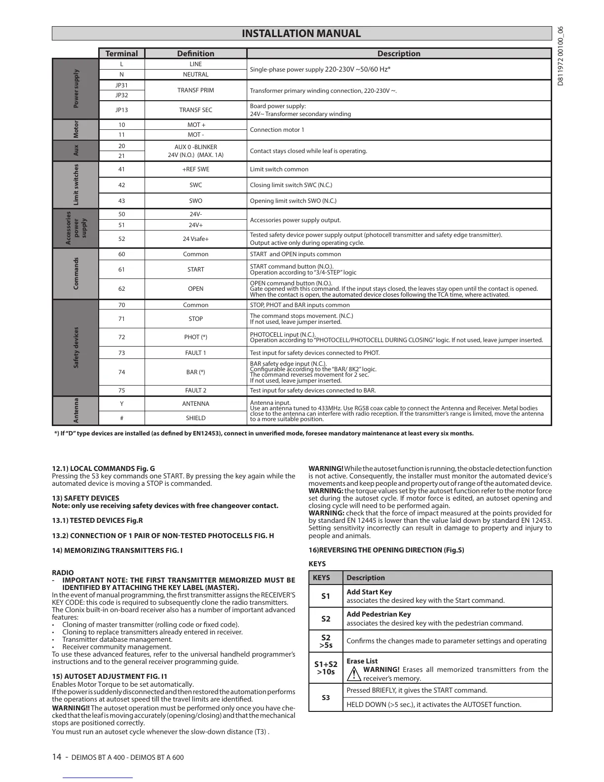
INSTALLATION MANUAL
Terminal Denition Description
Power supply
L LINE
Single-phase power supply
220-230V ~50/60 Hz*
N NEUTRAL
JP31
TRANSF PRIM
Transformer primary winding connection, 220-230V
~.
JP32
JP13 TRANSF SEC
Board power supply:
24V~ Transformer secondary winding
Motor
10 MOT +
Connection motor 1
11 MOT -
Aux
20
AUX 0 -BLINKER
24V (N.O.) (MAX. 1A)
Contact stays closed while leaf is operating.
21
Limit switches
41 +REF SWE Limit switch common
42 SWC Closing limit switch SWC (N.C.)
43 SWO Opening limit switch SWO (N.C.)
Accessories
power
supply
50 24V-
Accessories power supply output.
51 24V+
52 24 Vsafe+
Tested safety device power supply output (photocell transmitter and safety edge transmitter).
Output active only during operating cycle.
Commands
60 Common START and OPEN inputs common
61 START
START command button (N.O.).
Operation according to “3/4-STEP” logic
62 OPEN
OPEN command button (N.O.).
Gate opened with this command. If the input stays closed, the leaves stay open until the contact is opened.
When the contact is open, the automated device closes following the TCA time, where activated.
Safety devices
70 Common STOP, PHOT and BAR inputs common
71 STOP
The command stops movement. (N.C.)
If not used, leave jumper inserted.
72 PHOT (*)
PHOTOCELL input (N.C.).
Operation according to “PHOTOCELL/PHOTOCELL DURING CLOSING” logic. If not used, leave jumper inserted.
73 FAULT 1 Test input for safety devices connected to PHOT.
74 BAR (*)
BAR safety edge input (N.C.).
Congurable according to the “BAR/ 8K2” logic.
The command reverses movement for 2 sec.
If not used, leave jumper inserted.
75 FAULT 2 Test input for safety devices connected to BAR.
Antenna
Y ANTENNA
Antenna input.
Use an antenna tuned to 433MHz. Use RG58 coax cable to connect the Antenna and Receiver. Metal bodies
close to the antenna can interfere with radio reception. If the transmitter’s range is limited, move the antenna
to a more suitable position.
# SHIELD
*) If “D” type devices are installed (as dened by EN12453), connect in unveried mode, foresee mandatory maintenance at least every six months.
12.1) LOCAL COMMANDS Fig. G
Pressing the S3 key commands one START. By pressing the key again while the
automated device is moving a STOP is commanded.
13) SAFETY DEVICES
Note: only use receiving safety devices with free changeover contact.
13.1) TESTED DEVICES Fig.R
13
.2 CONNECTION OF 1 PAIR OF NONTESTED PHOTOCELLS FIG. H
14 MEMORIZING TRANSMITTERS FIG. I
RADIO
- IMPORTANT NOTE: THE FIRST TRANSMITTER MEMORIZED MUST BE
IDENTIFIED BY ATTACHING THE KEY LABEL (MASTER).
In the event of manual programming, the rst transmitter assigns the RECEIVER’S
KEY CODE: this code is required to subsequently clone the radio transmitters.
The Clonix built-in on-board receiver also has a number of important advanced
features:
To use these advanced features, refer to the universal handheld programmer’s
instructions and to the general receiver programming guide.
15 AUTOSET ADJUSTMENT FIG. I1
Enables Motor Torque to be set automatically.
If the power is suddenly disconnected and then restored the automation performs
the operations at autoset speed till the travel limits are identied.
WARNING!! The autoset operation must be performed only once you have che-
cked that the leaf is moving accurately (opening/closing) and that the mechanical
stops are positioned correctly.
You must run an autoset cycle whenever the slow-down distance (T3) .
WARNING! While the autoset function is running, the obstacle detection function
is not active. Consequently, the installer must monitor the automated device’s
movements and keep people and property out of range of the automated device.
WARNING: the torque values set by the autoset function refer to the motor force
set during the autoset cycle. If motor force is edited, an autoset opening and
closing cycle will need to be performed again.
WARNING: check that the force of impact measured at the points provided for
by standard EN 12445 is lower than the value laid down by standard EN 12453.
Setting sensitivity incorrectly can result in damage to property and injury to
people and animals.
16)REVERSING THE OPENING DIRECTION (Fig.S)
KEYS
KEYS Description
S1
Add Start Key
associates the desired key with the Start command.
S2
Add Pedestrian Key
associates the desired key with the pedestrian command.
S2
>5s
Conrms the changes made to parameter settings and operating
S1+S2
>10s
Erase List
WARNING! Erases all memorized transmitters from the
receiver’s memory.
S3
Pressed BRIEFLY, it gives the START command.
HELD DOWN (>5 sec.), it activates the AUTOSET function.
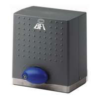
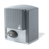
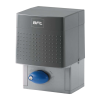
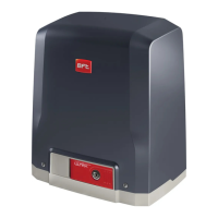
14 - DEIMOS BT A 400 - DEIMOS BT A 600
D811972 00100_06
 Loading...