Thank you for buying this product. Our company is sure that you will be more
than satised with the product’s performance.
Carefully read the “WARNINGS” pamphlet and the “INSTRUCTION BOOKLET”
which are supplied together with this product, since they provide important in-
formation regarding the safety, installation, use and maintenance of the product.
This product complies with recognised technical standards and safety regula-
tions. We declare that this product is in conformity with the following European
Directives: 2004/108/EEC, 2006/95/EEC and following amendments.
1) GENERAL OUTLINE
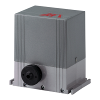
The E5 model consists of a compact electromechanical gearmotor with mini-
mum overall dimensions which can be installed on any post or pillar thanks to
its versatility. Gate locking in the closing position is guaranteed by an electric
lock. The reversibility of the gearmotor allows immediate manual manoeuvring
of the gate in case of emergency, by means of the appropriate personalised key
releasing the electric lock. Total anti-squash safety is provided by a multiple-disk
clutch and the end-of-stroke operation is set by a timer.
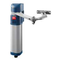
The gearmotor (g.1) is made up of : Motor single-block “M”, Epicycloidal reducing
gear “R”, Multiple-disk mechanical clutch “F”, Pushing arm “B”.
2) TECHNICAL SPECIFICATIONS
Power supply 230V~ ±10% 50Hz single-phase (*)
Motor 1400 min
-1
Max. power 200W
Reduction ratio 1/1296
Capacitor 8µF
Absorbed current 0,8A
Lubrication Permanent grease
Max. torque 300 Nm
Opening speed 22 s (~ 6,5 °/s)
Max. leaf weight 2000N (~200kg)
Max. leaf length 1.800mm
Max opening degrees 180° (with arm as shown in Fig. 10)
Impact reaction Multiple-disk mechanical clutch
Manual manoeuvre Electric lock release with key
No. manoeuvres in 24 h 50
Environmental conditions -10°C to +60°C
Degree of protection IP 44
Controller weight 8 kg
Dimensions See g.2
(*) Special voltages on request
3) INSTALLATION OF THE ACTUATOR
3.1) Preliminary checks
Check:
- That the structure of the gate is strong enough. The xing position must be
determined according to the leaf structure. In any case, the drive arm must
push against a reinforced point in the leaf;
- That the leaves can be moved manually without excessive eort for the whole
of their stroke;
- If the gate being installed is not new, check whether its components are worn.
Repair or replace any worn or damaged parts.
Automation reliability and safety are directly inuenced by the condition of the
gate structure.
3.2) Standard installation
Fig. 3 shows the standard installation position for Mod. E5. However, if the
automation must be tted onto a gate with a pedestrian access and with a leaf
with up to 1.4 m length, the opening speed can be increased by bringing the
gate fastening position “A” near to the hinge-pivot (g.4) or by shortening the
articulated lever “L2” (g.5).
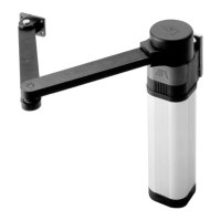
If the minimum value equal to 210mm indicated in the drawing of g.6 is not
available due to the presence of a wall in the corner, use a slide arm (g.7); in
this case, make sure that the length of the leaf does not exceed 1.6 metres and
its weight is 100 kg max.
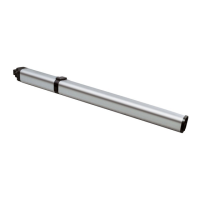
If the maximum value equal to 200mm (g.3) is not available due to a too large
gate-post, use version E5L with both arms “L1-L2” extended (g.8). For heavy gates
with leaves with up to 2 m length 200 kg weight, request an extended “L2” arm
(g.9) featuring increased power; in this case, the opening time will be longer
because the rotation degrees of lever “L1” are increased. If the automation must
be tted onto a gate with 180° angular opening (g.10) or there is no space in
the gate-post to mount the motor, a recess should be made in the leaf in corre-
spondence with the gate hinge-pivot (g.11); in this case the weight of the leaf
must not be supported by the gearmotor and the length of the single leaf must
not exceed 1.6 m and its weight not be greater than 100 kg.
WARNING! The controller mod. E5 must not be installed with the clutch unit
facing downward.
4) FITTING OF THE GEARMOTOR
To t the gearmotor supporting plate onto the gate-post proceed as follows:
- With a good electric welding (g. 12) if the gate-post in made of metal.
- If the gate-post is in brick, the plate must be set soundly into the post using
adequately sized cramps “Z” welded to the back of the plate (g. 13).
- If the gate-post is in stone and the gate is small and therefore does not require
excessive power to be opened, the plate can be mounted with four metal
expansion plugs “T” (g. 14).
- If the gate-post is in stone and a large gate is being installed it would be
better to weld the plate to a corner plate “C” xed with four expansion plugs
(g. 15).
- After fastening the anchoring plate, t the gearmotor (g. 16).
- Close the gate and loosen the clutch (g. 23). Position the drive arm so as to
create a pressing angle as shown in the gures for positioning.
- Temporarily lock the fastening element “A” (g. 17) to the leaf (using locking
pliers) and open the leaf manually.
Check that the drive arm does not cause any crushing or entanglement risks
when moving.
- Secure the fastening fork “A” to the leaf (g. 17) using the four threaded holes
“F” to be made in the selected position.
- Check that the arm is level (g. 18).
- In the case of gearmotors equipped with the slide arm Mod. E5S, the slide
“S” should be secured with its sliding slit facing the ground (g, 19); the slide
must be located at the maximum distance from the gate-post allowed by the
arm “L1”.
5) FITTING THE ELECTRIC LOCK
Due to the reversibility of the gearmotor, an electric lock must be tted.
The company supplies a special electric lock Mod. EBP (g. 20) which consists of
a continuous electromagnet with ground catch. This device remains energised
during the total operation time of the gearmotor so as the bolt “D” can reach
the closing limit stop lifted without creating any friction with the ground and
guaranteeing a smooth movement.
If the gates has two leaves, the leaf equipped with the electric lock should close last.
Use a control unit with closing delay adjustment for the second leaf.
6) GATE STOP LIMITS
It is compulsory to t the gate stop limits “F” (g.21), both in opening and closing
positions, to stop the strokes of the leaves in the desired positions.
7) ELECTRICAL PLANT SET-UP
Set the electrical plant as shown in g. 22 according to the current standards
for electrical plants CEI 64-8, IEC364, Harmonization HD384 and other national
regulations. Keep the power supply connections denitely separated from the
auxiliary connections (photocells, control devices, etc.).
Fig. 22 indicates the number of connections and the sections for 100 m. long
power supply cables. For distances of over 100 m., calculate the cable section
depending on the automation actual load.
The automation main components are the following (g. 22):
I Type approved omnipolar switch with 3,5 mm min. contact opening
provided with overload and short-circuit protection, used to break
the automation connection from the mains. If not present, provide the
automation with a type approved dierential switch with adequate
capacity and a 0.03 A threshold.
QR Control unit with built-in receiver
SPL Pre-heating board on the control panel for operation at temperatures
below -10° C (optional)
S Key selector
AL Blinker tuned in with antenna
M Actuators
E Electric lock
Fte,Fre Pair of outside photocells
Fti, Fri Pair of inside photocells with columns
T 1-2-4 channel transmitter
WARNING! For the connection of the accessories, please refer to the relevant
instruction manuals. The type of control boards and accessories must be suita-
ble for the intended use and in compliance with the current safety standards.
8) MOTOR TORQUE ADJUSTMENT (CLUTCH)
The motor torque adjustment is carried out in the gearmotor by means of the
mechanical multiple-disk clutch (g.23).
The adjustment of the clutch must be carried out by qualied personnel (instal-
ler) and includes the calibration of the clutch to the minimum force needed to
complete full opening and closing strokes. The calibration must never exceed the
values of the pushing force measured on the leaf edge according to the national
standards in force. In Italy the admitted value is equal to 150N.
WARNING! Do not secure completely the adjustment screw of this device;
E5-
9
 Loading...