INSTALLATION MANUAL
1) FOREWORD
ERIS A30 is a device that can be used on sliding gates and provides a
solution to the problem of connecting safety edges located on the mo-
ving leaf with the door’s control unit. ERIS A30 comprises two transcei-
ver units that communicate with each other through infrared signals.
Communication is coded using special safety techniques so that the
whole device gets a category 2 fault detection rating according to stan-
dard EN 954-1 and can therefore be used in PSPE systems in conformity
with standard EN 12978.
ERIS A30 comprises 2 units:
- ERIS A30 TX, which is powered by a long-life battery, should be atta-
ched to the moving leaf and can be connected with the safety edge,
which can either be optical (using the STR accessory = rubber prole
max. 2.5m) or resistive with a constant 8k2 resistance.
- ERIS A30 RX should be attached to the xed part and is wired to the
gate’s control unit.
ERIS A30 is designed to be connected as a tested device. In addition to
working as a connection system between a safety edge and the control
unit, the device can also be used as a presence detector and hence as a
category D device according to standard EN 12453. To use ERIS A30 as
a type D device, ERIS A30 TX and ERIS A30 RX merely have to communi-
cate across the opening (See Fig. B Ref.1).
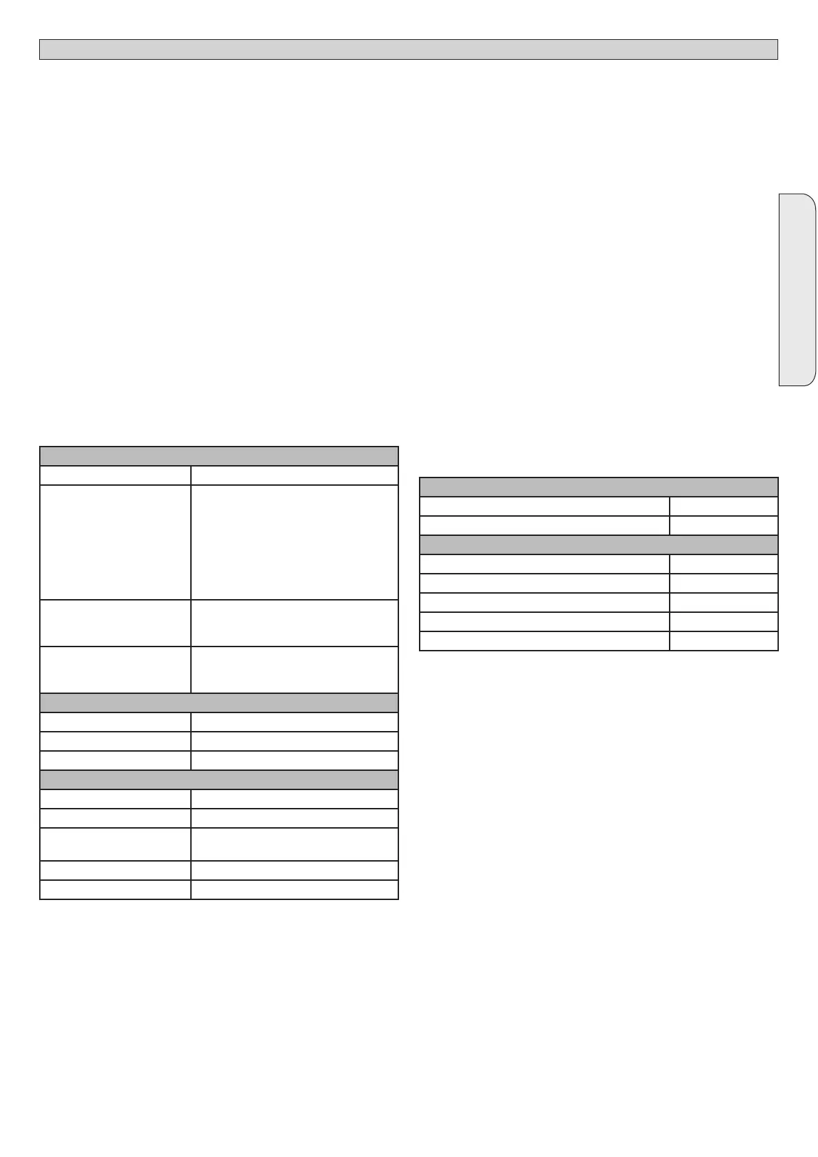
2) TECHNICAL SPECIFICATIONS (SPECIFICATIONS AT 20°C)
ERIS A30 TX
Power supply 3.6V Type C lithium battery. Capacity 7.5Ah
Battery life
Wiring with test: up to 5 years
(Life estimated based on installation
with 4m travel at speed of 9 m/min, TCA
10 S, 30 operations/day with optical sa-
fety edge up to 2.5 m and temperature
of +20°C).
Wiring with no test: up to 1 year
Response time from when sa-
fety edge is pressed in tested
mode
<35mS
Response time from when
safety edge is pressed in non-
tested mode
<100mS
ERIS A30 RX
Supply voltage 24 V~/=
Current demand Standby 20mA / max. 36mA
Contact capacity 30V, 1A
ERIS A30 TX + ERIS A30 RX
Protection rating IP45
Operating temperature -20/+55°C
Max range
(reduced in case of fog/rain)
15 m with jumper JP1 open TX,
30 m with jumper JP1 closed TX
Dimensions 130X45X43 (HxLxD)
Category according to EN 954-1
Cat 2
3) CORRECT ALIGNMENT Fig. A - B
4) HOLES FOR INSTALLATION Fig. C
5) RUNNING ERIS A30 RX (Fig. D) and ERIS A30 TX (Fig. E) CABLES:
- through hole in back Ref. 1A
- through cable clamp Ref. 1B
Fasten the safety edge to the edge of the leaf following the directions
given in the instruction manual for the safety edge being used.
6) WIRING Fig. F
If no safety circuit fault test circuit is being used, qualied personnel
must be brought in to check that the device is in proper working order
at least once every 6 months.
7) INSPECTION Fig. G-H
Once inspection is complete, perform a few test cycles and check that:
a) When the safety edge is pressed, the automated system reacts as it
should.
b) When communication is broken between ERIS A30 RX and ERIS A30
TX by placing an obstacle between them, the automated system
reacts as it should.
c) When the previous 2 operating conditions are not encountered,
the operation is completed correctly.
8) WARNING! If the installation situation diers from the one featured
in the manual, refer to operation table 1. Also make sure that the
gate does NOT CREATE hazardous situations when it moves.
See TABLE Fig.I.
WARNING!
To connect the relay contacts to the fault test circuit, you must refer
to the wiring diagrams of the tested devices given in the instruction
manual for the control unit being used.
WARNING!
If other devices using infrared beams (photocells) are present, they
may interfere with communication. In the event a number of pairs of
photocells are installed in the same area, check that there is no interfe-
rence between them. In the event the ERIS A30 communication signal
is aected by interference from another ERIS A30 infrared signal, switch
the automated system to a safe state by opening both contacts.
9) SAFETY EDGE THAT CAN BE CONNECTED TO ERIS A30 TX
OPTICAL SAFETY EDGE
Sensors STR
Maximum safety edge length 2,5m
RESISTIVE SAFETY EDGE
Rated resistance 8k2
Upper trigger threshold >22000
Maximum standby resistance 18000
Lower trigger threshold < 2200
Minimum standby resistance 4700
ENGLISH
ERIS A30- 11
D811992 00100_01
 Loading...