- 10 -
ENGLISH
1.5 OVERALL DIMENSIONS
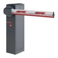
RIGHT barrier
LEFT barrier
2.1 INSTALLATION EXAMPLE
2.2 SECURING THE STRUCTURE
1) Single-phase line (2+G) x 1.5mm
2) Transmitting Photocell 2 x 0.5 mm
3) Receiving Photocell 4 x 0.5 mm
4) Key selector switch 3 x 0.5 mm
5) Receiver 4 x 0.5 mm
5) Antenna RG58
6) Magnetic coil
347347
54
1030
870
40106
338338
5
6
3
1
2
4
Check the direction of travel indi-
cated on the template, for precise
overlapping of the rounded cor-
ners of the barrier body
Arrange in the foundation cor-
rugated tubes for power supply
and system cables (not supplied)
Cement
(not supplied)
200
200
500
500
400
Template
Cramps
It is recommended to re-
move the template before
securing the barrier
19 mm
1. General information / 2. Installation
EN