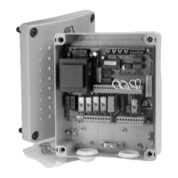
The RIGEL 4 is a microprocessor-controlled unit designed to manage one or two motors, each with a power output of up to 375 W. It is supplied with an instruction manual providing important information on safety, installation, operation, and maintenance. The product complies with recognized technical standards and safety regulations, specifically European Directives 89/336/EEC, 73/23/EEC (amended by RL 91/263/EEC, 92/31/EEC, and 93/68/EEC). For wiring and installation, it is crucial to refer to current standards and follow best technical practices to ensure good performance.
Function Description
The control unit's configuration and calibration are managed via Dip-switches and trimmers. The functions of these controls and their effects are detailed in the manual, with their arrangement shown in Figure 1. For ease of maintenance and replacement, the board features a removable terminal board with 40 terminals, as illustrated in the wiring diagram in Figure 2. Pre-wired jumpers are included to simplify installation, connecting terminals 31-33, 32-33, 33-34, 35-36, 36-37, 38-39, and 39-0.
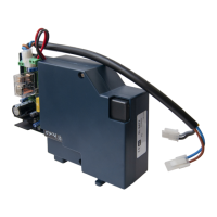
An optional SSR4 board can be fitted to control two traffic lights, with its operation and specifications detailed in a specific section and its wiring diagram shown in Figure 3. The RIGEL 4 can also be supplemented with an additional SPL board (Figure 4) and an automatic thermostat for motor pre-heating, with the wiring diagram in Figure 5.
The unit features separate limit switch inputs for both closing and opening maneuvers for each motor. If the sensing edge is activated, the gate's movement direction reverses for 3 seconds, and a subsequent command continues the reverse movement. A 12Vac electric lock can be connected, with power excitation lasting approximately 3 seconds. A continuous duty EBP electric lock can be connected in parallel to the 230Vac blinker. A courtesy light output is provided, with a time range of up to 90 seconds after the last command.
Important Technical Specifications
- Mains Power Supply: 230V±10% 50Hz (other voltages available on request)
- Mains Insulation/Low Voltage: > 2MOhm 500Vdc
- Dielectric Strength/Low Voltage: 3750Vac per 1 minute
- Motor Output Current: 5A max
- Motor Relay Switching Current: 15A
- Max. Motor Power: 1 motor 375W, 2 motors 375W + 375W
- Courtesy Light: Max 150W, time set up to 90 seconds from last command
- Power Supply for Accessories: 24Vac (0.5A maximum absorption)
- Electric Lock Output: 12Vac (2A maximum absorption)
- Gate-Open Warning Light: 24Vac 3W max
- Blinker: 230V 40W max
- Fuses: See Figure 1
Terminal Board Connections (JP1, JP6, JP4, JP5):
- JP1 (1-2): Power supply 230Vac±10%, 50-60Hz (1 phase, 2 neutral).
- JP6 (3-4-5): Connection motor 1 (may be delayed in opening); terminals 4-5 phase and capacitor, terminal 3 neutral.
- JP6 (6-7-8): Connection motor 2 (may be delayed in closing); terminals 7-8 phase and capacitor, terminal 6 neutral.
- JP6 (9-10): Output for 230Vac flashing beacon (40W max) and for electronic lock EBP 230Vac.
- JP6 (11-12): Courtesy light 230Vac (150W max) delayed for 90s after the last operation.
- JP4 (13-14): Gate open warning light 24V (3W max).
- JP4 (15-16): 24Vac output for photocells etc. (6W max, 25mA).
- JP4 (17-18): Output for 12Vac lock (2A max).
- JP4 (19-20): Antenna input (19 signal, 20 braiding).
- JP4 (21-22): Output of second radio channel (if 2nd channel receiver installed).
- JP5 (23-24): Start command (n.o.), START I for traffic light.
- JP5 (24-25): Start command (n.o.), START E for traffic light.
- JP5 (26-27): Pedestrian gate - start command.
- JP5 (28-30): Open command (n.o.).
- JP5 (29-30): Close command (n.o.).
- JP5 (31-33): Stop command (n.c.).
- JP5 (32-33): Photocell input / safety circuit (n.c.).
- JP5 (33-34): Second safety circuit. Safety edge.
- JP5 (35-36): Open limit switch motor 1 (n.c.).
- JP5 (36-37): Close limit switch motor 1 (n.c.).
- JP5 (38-39): Open limit switch motor 2 (n.c.).
- JP5 (39-40): Close limit switch motor 2 (n.c.).
Usage Features
The RIGEL 4's functioning logic is configured via Dip-switches:
- Dip-switch 1 (Photocells - FCH):
- ON: Inhibits photocell operation during opening; reverses movement immediately during closing if an obstacle is detected.
- OFF: Stops gate movement during closing if an obstacle is detected, then opens once the obstacle is removed. Stops immediately during opening if an obstacle is detected, then completes opening once removed.
- Dip-switch 2 (Impulse Blocking Device - IBL):
- ON: Start impulse has no effect on opening.
- OFF: Start impulse during opening stops the gate (Dip 6 OFF) or reverses (Dip 6 ON).
- Dip-switch 3 (Automatic Closing - TCA):
- ON: Activates automatic closing after a dwell time set by the TCA trimmer. This occurs when the gate reaches the opening end, working time on opening has elapsed, or the gate is stopped during opening by a start impulse.
- OFF: Inhibits automatic closing.
- Dip-switch 4 (Ram Blow - HAMMER):
- ON: Pushes on closing for ~2 seconds before opening, aiding electric lock release.
- OFF: Inhibits ram blow.
- Dip-switch 5 (Motor 1 Opening Delay - DELAY OPEN):
- ON: Motor 1 starts with a ~3-second delay on opening.
- OFF: Motor 1 starts with a ~0.5-second delay on opening.
- Dip-switch 6 (2 or 4-step Logic - 2P/4P):
- ON (2-step logic): A start impulse while the gate is moving inverts the movement direction.
- OFF (4-step logic): A start impulse while the gate is moving stops it; a subsequent impulse inverts the movement direction. (Note: Start impulse has no effect if Dip 2 is OFF during opening).
- Dip-switch 7 (Pre-alarm - PREAL):
- ON: Blinker lights up ~3 seconds prior to motor start.
- OFF: Blinker lights up as soon as motors start.
- Dip-switch 8 (Block Persistence - BLOCK):
- ON: If motors remain still in the complete open/close position for over an hour, they are pushed for ~3 seconds in the end of stroke direction. This function is performed hourly. (Note: For oil-hydraulic motors, this compensates for oil volume decrease due to temperature changes during long pauses and keeps grease slightly heated in electromechanical actuators for swing gates. WARNING: Do not use for sliding gates or without appropriate mechanical blocks).
- OFF: Inhibits block persistence.
- Dip-switch 9 (Reduced or Standard Working Time Range - S.TW):
- ON: Working time TW between 1-40 seconds (TW.PED from 1-20 seconds).
- OFF: Working time TW between 30-180 seconds (TW.PED from 15-90 seconds).
- Dip-switch 10 (Gate-Open/Close Control - U.P.):
- Operates on signals connected to terminals 28-29.
- ON (Hold-to-run): Maneuver lasts as long as the control key is pressed.
- OFF (Separate gate-open/close automatic control): One impulse opens the gate if closed and vice versa.
Functions Controlled by Trimmers:
- TW.PED: Adjusts working time for pedestrian access (motor 2) or partial working time for sliding gate (pedestrian and vehicular access).
- TW: Adjusts working time during both opening and closing.
- TCA: Adjusts dwell time before automatic re-closing.
- T.DELAY: Adjusts delay time on closing of motor 2.
LED Functions:
The RIGEL 4 control unit features a series of LEDs to detect system malfunctions:
- LINE (DL1): Stays on with mains supply and when fuse F2 is working.
- START I (DL2): Lights up when an internal start command is given.
- START E (DL3): Lights up when an external start command is given or when the first channel of the receiver is activated.
- PED (DL4): Lights up when a start command for pedestrian access is given.
- OPEN (DL5): Lights up when a manual opening control is given.
- CLOSE (DL6): Lights up when a manual closing control is given.
- STOP (DL7): Switches off when a block command is given.
- PHOT (DL8): Switches off when photocells are not aligned or obstacles are detected.
- BAR (DL9): Switches off when the sensitive edge is activated.
- SWO1 (DL10): Switches off when gate (motor 1) reaches its complete opening position (if equipped with a limit switch).
- SWC1 (DL11): Switches off when gate (motor 1) reaches its complete closing position (if equipped with a limit switch).
- SWO2 (DL12): Switches off when gate (motor 2) reaches its complete opening position (if equipped with a limit switch).
- SWC2 (DL13): Switches off when gate (motor 2) reaches its complete closing position (if equipped with a limit switch).
- M1 (DL15): Lights up when motor 1 is activated (on opening or closing).
- M2 (DL16): Lights up when motor 2 is activated (on opening or closing).
- DL14: Direction indicator LED: lights up when the gate is closing.
Maintenance Features
After connecting the control unit to the mains with pre-wired jumpers, ensure proper functionality by checking if the following LEDs light up: LINE, STOP, PHOT, BAR, SWO1, SWC1, SWO2, SWC2. This quick check is recommended before installation to identify any malfunctions.
SSR4 Traffic Light Board (Optional):
This board is exclusively for the RIGEL 4. It manages two traffic lights (one red, one green) according to standard automatic gate logic. Additional options can be set via Dip-switches on the SSR4 board. The gate and traffic light can be controlled by two commands:
- Internal START: (given when the gate is closed) Opens the gate, switches on the red light outside, and the green light inside when the gate is open.
- External START: (given when the gate is closed) Opens the gate, switches on the red light inside, and the green light outside when the gate is open.
During opening and closing, both red lights are illuminated.
Important Note for Traffic Light System:
Provide signals to limit speed and encourage slow progress. For correct command sequence:
- Position traffic light 2 inside the gate and traffic light 1 outside the gate (Figure 3).
- Activate BLI, 2-step logic, and pre-alarm functions (Dip 2, Dip 6, Dip 7 all to ON) on RIGEL 4.
- The only command for outside access must be the external START (already on the receiver's first channel).
- For installations with traffic lights not visible from each other, it is recommended to use the special microprocessor of RIGEL 4, where Dip 2 functions as:
- ON: Impulse blocking device active on opening.
- OFF: Impulse blocking device active on opening and during the TCA phase (if TCA is on).
Terminal Board Connections for SSR4:
-
- Phase
-
- Red light of traffic light 1
-
- Red light of traffic light 2
-
- Green light of traffic light 1
-
- Green light of traffic light 2
Dip-switch 1 (SSR4) - Inhibits blinking function at movement start:
- ON: Inhibits blinking.
- OFF: Activates blinking at movement start (operation time 5 sec).
Dip-switch 2 (SSR4) - Permanent red light with gate closed:
- ON: Activates red lights when the gate is closed.
- OFF: Switches off lights when the gate is closed.
Signals provided by the SSR4 board:
Red and green LEDs for traffic light 1 and traffic light 2.
Luminous signal for each traffic light:
- Green light: access permitted.
- Fixed red light: access not permitted.
- Flashing red light: gate movement start; access not permitted.
- N.B.: Movement reverse on closing does not enable the green light; wait until the gate is completely closed before giving the Start command.