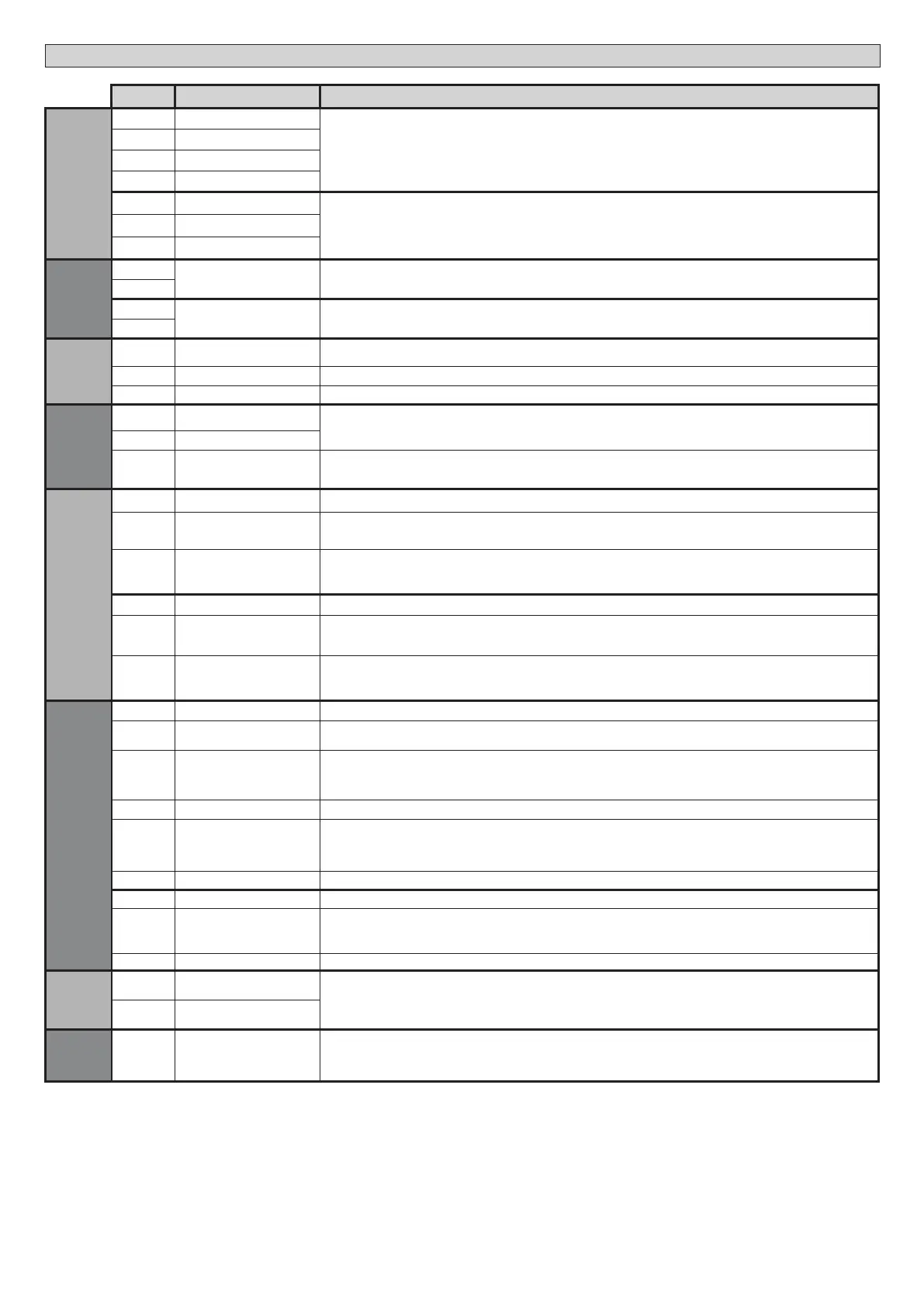
Terminal Denition Description
Power supply
L1 LINE - R
Three-phase Power supply 380-400V, 50-60Hz.
Fig. F
L2 LINE - S
L3 LINE - T
N NEUTRAL
L1
LINE - R
Three-phase Power supply 220-230V, 50-60Hz.
Fig. F
L2 LINE - S
L3
LINE - T
Aux
20
LIGHT 230V Flashing light 230V output max. 40W.
21
26
AUX 3 - FREE CONTACT (N.O.)
(Max. 24V 3W)
Contact N.O. (24V~/3W max).
Can only be used with second channel of radio-receiver plugged into relevant connector.
27
ENCODER
41 + REF SWE
Limit switch common
Pass the connection of the common limit switch through the N.C. contact (95-96) of the K0 thermal relay
42 SWC Closing limit switch SWC (N.C.).
43 SWO Closing limit switch SWO (N.C.).
Accessories
power supply
50 24V-
Accessories power supply output.
51 24V+
52 24 Vsafe+
Tested safety device power supply output (photocell transmitter and safety edge transmitter).
Output active only during operating cycle.
Commands
60 Common IC 1 and IC 2 inputs common
61 IC 1
Congurable command input 1 (N.O.) - Default START E.
START E / START I / OPEN / CLOSE / PED / TIMER / TIMER PED
Refer to the “Command input conguration” table.
62 IC 2
Congurable command input 2 (N.O.) - Default PED.
START E / START I / OPEN / CLOSE / PED / TIMER / TIMER PED
Refer to the “Command input conguration” table.
63 Common IC 3 and IC 4 inputs common
64 IC 3
Congurable command input 3 (N.O.) - Default OPEN.
START E / START I / OPEN / CLOSE / PED / TIMER / TIMER PED
Refer to the “Command input conguration” table.
65 IC 4
Congurable command input 4 (N.O.) - Default CLOSE.
START E / START I / OPEN / CLOSE / PED / TIMER / TIMER PED
Refer to the “Command input conguration” table.
Safety devices
70 Common STOP, SAFE 1 and SAFE 2 inputs common
71 STOP
The command stops movement. (N.C.)
If not used, leave jumper inserted.
72 SAFE 1
Congurable safety input 1 (N.C.) - Default PHOT.
PHOT / PHOT TEST / PHOT OP / PHOT OP TEST / PHOT CL / PHOT CL TEST / BAR / BAR TEST / BAR 8K2
2 / BAR OP / BAR OP
TEST / BAR 8K2 OP / BAR CL / BAR CL TEST / BAR 8K2 CL.
Refer to the “Safety input conguration” table.
73 FAULT 1 Test input for safety devices connected to SAFE 1.
74 SAFE 2
Congurable safety input 2 (N.C.) - Default BAR.
PHOT / PHOT TEST / PHOT OP / PHOT OP TEST / PHOT CL / PHOT CL TEST / BAR / BAR TEST / BAR 8K2
/
BAR OP / BAR OP
TEST / BAR 8K2 OP / BAR CL / BAR CL TEST / BAR 8K2 CL
Refer to the “Safety input conguration” table.
75 FAULT 2 Test input for safety devices connected to SAFE 2.
76 Common SAFE 3 input common
77 SAFE 3
Congurable safety input 3 (N.C.) - Default PHOT OP.
PHOT / PHOT TEST / PHOT OP / PHOT OP TEST / PHOT CL / PHOT CL TEST / BAR / BAR TEST
/ BAR OP / BAR OP TEST /
BAR CL / BAR CL TEST.
Refer to the “Safety input conguration” table.
78 FAULT 3 Test input for safety devices connected to SAFE 3.
Antenna
Y ANTENNA
Antenna input.
Use an antenna tuned to 433MHz. Use RG58 coax cable to connect the Antenna and Receiver. Metal bodies close to the
antenna can interfere with radio reception. If the transmitter’s range is limited, move the antenna to a more suitable position.
# SHIELD
Internal
wiring
ABCD
EFGH
RST
Internal wiring See wiring Fig. P-Q
D812213 00100_08
22 - SP 3500 - SP 3500 SF
INSTALLATION MANUAL
 Loading...