4 SUB-UL
D811290_04
MANUEL D’UTILISATION
FRANÇAIS
Nous vous remercions pour avoir choisi ce produit. Nous sommes certains qu’il vous rendra le service nécessaire pour vos besoins. Lisez attentivement la brochure
“AVERTISSEMENTS” et le “MANUEL D’INSTRUCTIONS” qui accompagnent ce produit, puisqu’ils fournissent d’importantes indications concernant la sécurité, l’in-
stallation, l’utilisation et l’entretien. Ce produit est conforme aux règles reconnues de la technique et aux dispositions de sécurité. Nous conrmons qu’il est conforme
aux normes suivantes: CAN/CSA-C22.2 N° 247-92 UL Std. N° 325 (Certicat 1002906 du 16 octobre 2000).
1) GENERALITES
L’opérateur hydraulique SUB est la solution idéale pour les applications enterrées sous les gonds. Il résout brillamment les problèmes esthétiques de la motorisation.
L’actionneur SUB est réalisé dans un seul monobloc étanche qui contient l’unité hydraulique - vérin qui permet d’obtenir une installation complètement enterrée
et sans aucune connexion hydraulique. La fermeture du portail est maintenue par une serrure électrique ou bien par le blocage hydraulique dans les versions SUB
dotées de ce dispositif. Les versions dotées de ralentissements permettent une approche en ouverture et en fermeture sans claquements. La force de poussée peut
être réglée avec une précision extrême au moyen de deux soupapes de dérivation qui représentent la sécurité anti-écrasement. Le fonctionnement à la n de course
est réglé électroniquement sur le tableau de commande au moyen d’un temporisateur. En enlevant un bouchon spécial sur la couverture, il est possible d’accéder
facilement au déblocage d’urgence, qui est activé avec la clé spéciale fournie en dotation.
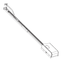
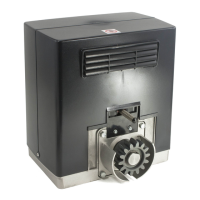
2) PARTIES PRINCIPALES DE L’AUTOMATISME
Actionneur hydraulique monobloc (g.1) constitué par:
M) Moteur monophasé 2 pôles protégé par un disjoncteur thermique.
P) Pompe hydraulique lobée.
D) Distributeur avec soupapes de réglage.
PC) Vérin crémaillère - pignon.
Composants fournis en dotation: clé de déblocage et de réglage by-pass - bague cannelée - manuel d’instructions.
ATTENTION: L’actionneur peut être droit ou gauche et par convention on regarde le portail du côté interne (direction d’ouverture). L’actionneur droit ou gauche
peut être identié par la position du pivot de déblocage «PST». La g.1 illustre un actionneur gauche.
3) ACCESSOIRES
- Caisse de fondation portante CPS (prédispose à la motorisation).
- Caisse de fondation non portante CID.
- Bras à coulisse BSC (pour le montage hors des gonds).
4) OUVERTURE MANUELLE
En cas d’urgence, par exemple lors d’une coupure de courant, le portail doit être ouvert manuellement.
5) UTILISATION DE L’AUTOMATISME
L’automatisme pouvant être commandé à distance par radiocommande ou bouton de Start, il est indispensable de contrôler souvent le bon fonctionnement de
tous les dispositifs de sécurité. Pour toute anomalie de fonctionnement, intervenir rapidement en s’adressant à un personnel qualié. Il est recommandé de tenir les
enfants loin du rayon d’action de l’automatisme.
6) ENTRETIEN
ATTENTION: Tous les deux ans, remplacer complètement l’huile de chaque actionneur. N’utiliser que de l’huile du même type (IDROLUX).
7) DEMOLITION
L’élimination des matériaux doit être faite en respectant les normes en vigueur. En cas de démolition de l’automatisme, il n’existe aucun danger ou risque particulier
dérivant de l’automatisme. En cas de récupération de matériaux, il est opportun de les séparer selon le genre (parties électriques - cuivre - aluminium - plastique - etc.).
8) DEMONTAGE
Si l’automatisme est démonté pour être ensuite remonté ailleurs, il faudra:
- Couper l’alimentation et débrancher toute l’installation électrique.
- Enlever le motoréducteur de la base de xation.
- Démonter le tableau de commande, s’il est séparé, et tous les composants de l’installation.
- Si des composants ne peuvent pas être démontés ou s’ils sont endommagés, il faudra les remplacer.
8) MAUVAIS FONCTIONNEMENT: CAUSES et REMEDES.
Pour toute anomalie de fonctionnement non résolue, couper l’alimentation au système et demander l’intervention de personnel qualié (installateur). Pendant la
période de hors service, activer le déblocage manuel pour permettre l’ouverture et la fermeture manuelle.
D811290_04
 Loading...