page 6 Installation and Operation Guide Qt X Sound Masking System
Installation
The Qt X 300/300D and Qt X 600/600D may be installed on a wall with the
included hardware. An optional Rack Mount accessory kit is available to install
the unit in a rack (Instructions can be found on pages 33-34).
NOTE: It is up to the installer to determine the safest, most secure means of installing
the Qt X on to a wall or other vertical surface. Consult any local building/safety codes as
required.
NOTE: Equipment installation should be planned such that audio and network sources are
in place prior to Qt X and emitter installation. Emitters should be tested upon installation
with sound masking audio active to ensure proper functionality.
Wall-mount installations:
1. Place the wall mount where it is to be mounted and mark the hole locations.
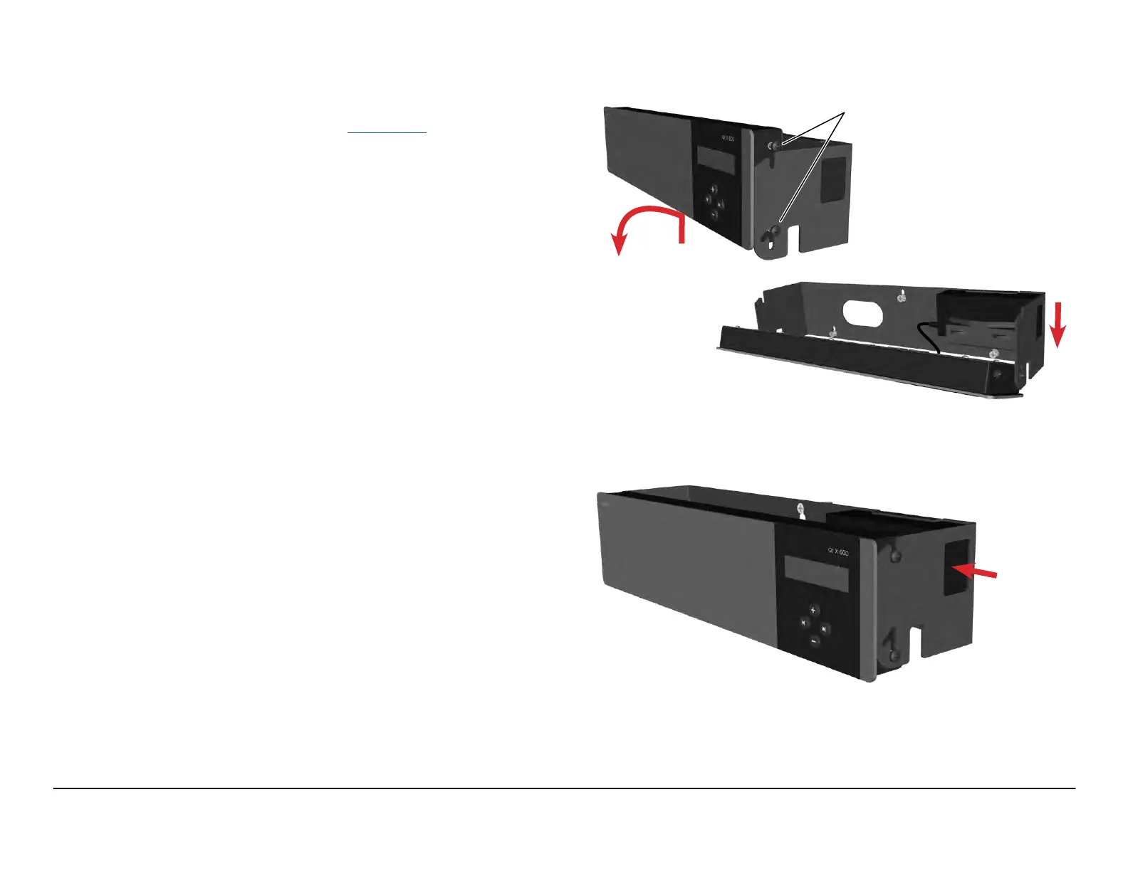
The control module hinges forward for wall mounting and cable installation.
To hinge forward, loosen the screws on both sides, lift it up to disengage the
top screws, and rotate forward as shown (Figure1).
IMPORTANT: If using the wall mount bracket as a template to drill into the wall,
remove the bracket from the Qt X prior to drilling to avoid getting debris in the
Qt X connectors and ports.
2. If installing into drywall/sheet rock, drill the mounting holes with a 1/4" drill bit,
and insert plastic mounting anchors into the drywall/sheet rock.
3. Install the screws into the plastic anchors leaving enough room for the bracket
to be hung on the screw heads. Place the bracket so the screw heads t
into the keyholes and then move the bracket down to capture the screws.
Tighten the screws to secure the bracket to the wall.
NOTE: If the Qt X was removed from the wall bracket, reinstall the screws
that secure it to the wall bracket. The controller can be rotated down to
make it easier to tighten the mounting screws.
4. Connect all wiring/cabling as described in Wiring & Connections. Rotate the
Qt X up and move down into the operating position to lock into place. Tighten
the side screws to secure it to the bracket. See Figure 2.
Loosen Screws
Figure 1. Mount unit / wall bracket
Figure 2. Controller in operating position
plug power
cord into
power supply

 Loading...