Qt X Sound Masking System Installation and Operation Guide page 7
2
1
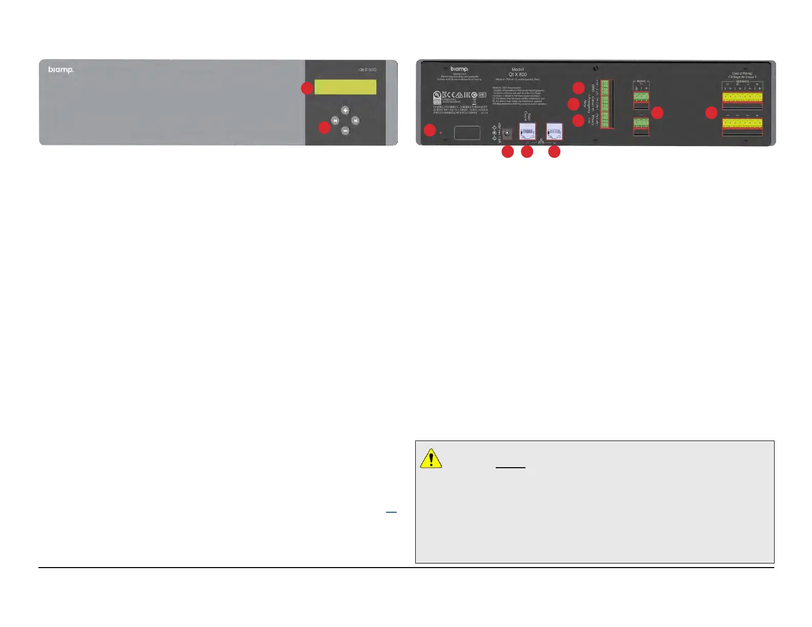
QT X 800/ 800D
Qt X Qt X800/800D Front Panel
5
8
7
11
4
3
10
6
9
Qt X 800/800D Rear Panel
1. LCD Display
The LCD display indicates system statuses and parameters. Users may navigate
through the display to view the current IP address and network mask of the
device, view current operating mode of the device (unconfigured, configured,
updating firmware, etc.) and view any faults present.
2. Function/Navigation Buttons
Function/navigation buttons allow navigating through information provided in the
LCD display.
3. Factory Reset
Insert pin to depress the switch, press and hold for 10 seconds. This will return
the unit to factory settings, cause all configuration to be cleared and the device
to reboot.
4. Power Connector
Connection for an external 48V power supply (not included).
5. Network Control Port (PoE+)
The RJ45 port connector for a PoE+ Class 4 power supply must be ordered
separately (Biamp part# 900.0004 POE29U-1AT(PL)D-R). Power can also be
supplied by a Type 2 PoE+ enabled network switch. In dual cable mode this is
the media port, but in single cable mode it carries both control and media.
6. Network Media Port
RJ45 Gigabit Ethernet port connectors support AVB and Dante media streams
(Dante is only supported on 800D models). In dual cable mode this is the default
control port. In single cable mode this port is disabled.
7. 4-Pin Logic I/O - 2 ports
Two triggers for zone muting or indication for paging application. See page 13
for additional information.
8. 4-Pin Contact Closure - 2 inputs
This contact closure is provided in order to mute audio and sound masking in
the zone or system in the event of a fire emergency or request to page. These
inputs should be connected to the fire alarm panel (port 1) or paging system
(port 2 - configured as Push-to-Talk).
9. 4-Pin Privacy Light Output - 2 outputs
The privacy lights ports enable connections to (2) privacy light panels which
indicate when sound masking is enabled in a certain zone. Each can be assigned
to a different zone when configuring the system in the software or web interface.
10. 3-Pin MIC/Line Audio Inputs - 2 inputs
Two MIC/line audio inputs may be connected to an external audio source such
as a music player or an external paging controller. This allows distribution of
networked audio throughout the connected zones.
11. Speaker Outputs (x8)
The Qt X 800 supports up to eight outputs of sound masking and audio. Speaker
connections are made 2-wire connections to the yellow euroblock connectors.
Each output can accommodate (1) 4Ω DS1320 active emitter or (1-2) 8Ω DS1357
or (1) 4Ω DS1398 speaker (when using 2 loudspeakers, they must be connected
in parallel for a single 4Ω output).
VERY IMPORTANT: When installing the Qt X 800 controllers in a plenum
space it is critical that the serial numbers be recorded on the design drawing
as they are installed. Also, the loudspeakers must be documented as they are
placed and plugged into the corresponding output ports on the controller. The ceiling
will likely be closed up when the system is commissioned so visual verication of a
device location isn't possible. It is very important to know exactly which controller,
output and loudspeaker is being addressed when setting sound masking or EQ levels
as you are moving around the facility. Once the system devices are discovered with the
software or web UI, it is also important to name them (and the outputs) appropriately -
referencing the location and/or drawing designation.

 Loading...