Do you have a question about the Biamp Vocia DS-4 and is the answer not in the manual?
This document outlines a system design template for a cruise ship, focusing on Vocia products for a vessel-wide paging and evacuation system, background music (BGM), and ambient noise compensation (ANC). The Vocia system is presented as a highly reliable, scalable, and flexible solution with excellent audio quality, designed to meet current and future communication requirements. Its decentralized architecture, with digital signal processing in all endpoints, eliminates single points of failure and facilitates system expansion. The design emphasizes the critical need for system availability and safety measures in large public areas, particularly for providing clear evacuation directions during emergencies.
The system design incorporates several key functionalities:
The following Biamp Vocia equipment is used in this project:
The LSI-16e's functionality is tailored to EN 54-16 European life safety standards, but it, along with the CI-1, is applicable for highly reliable and fault-tolerant voice evacuation systems even without EN 54-16 compliance. The CI-1 facilitates connectivity to the Fire/Evacuation System (CIE) for bi-directional control and monitoring. Extra contact closure inputs on the LSI-16e are used for scheduled fire drills and system testing in specific areas.
Vocia supports two network communication modes:
All Vocia devices are set to unity gain by default, allowing the system to start working with minimal adjustments once the configuration file is loaded.
| Brand | Biamp |
|---|---|
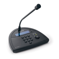
| Model | Vocia DS-4 |
| Category | Microphone |
| Language | English |