Technical Status: 11/2010 Page 5
Gas Detector
Operating and Installation Instructions
ExDetector HC 150 / HC 150-K
Adjustment
Important note!
The relevant regulations for work in areas where there is an explosion
hazard must be observed without fail.
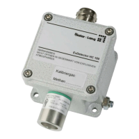
The following accessories and equipment are required:
● Voltmeter
● Test gas set consisting of:
- 1 x Minican of test gas (e.g. 40% LEL)
- 1 x Minican of synthetic air
- Pressure regulator unit with regulating valve and flow meter.
- Test gas cap (see Accessories)
- Measurement leads (see Accessories)
Adjustment
● Remove the cover from the housing.
Important: before opening make sure that an explosive atmosphere is not
present.
● Fit test-gas cap to the sensor.
● The flow rate of the two gases should be 10 to 15 l/h (second graduation).
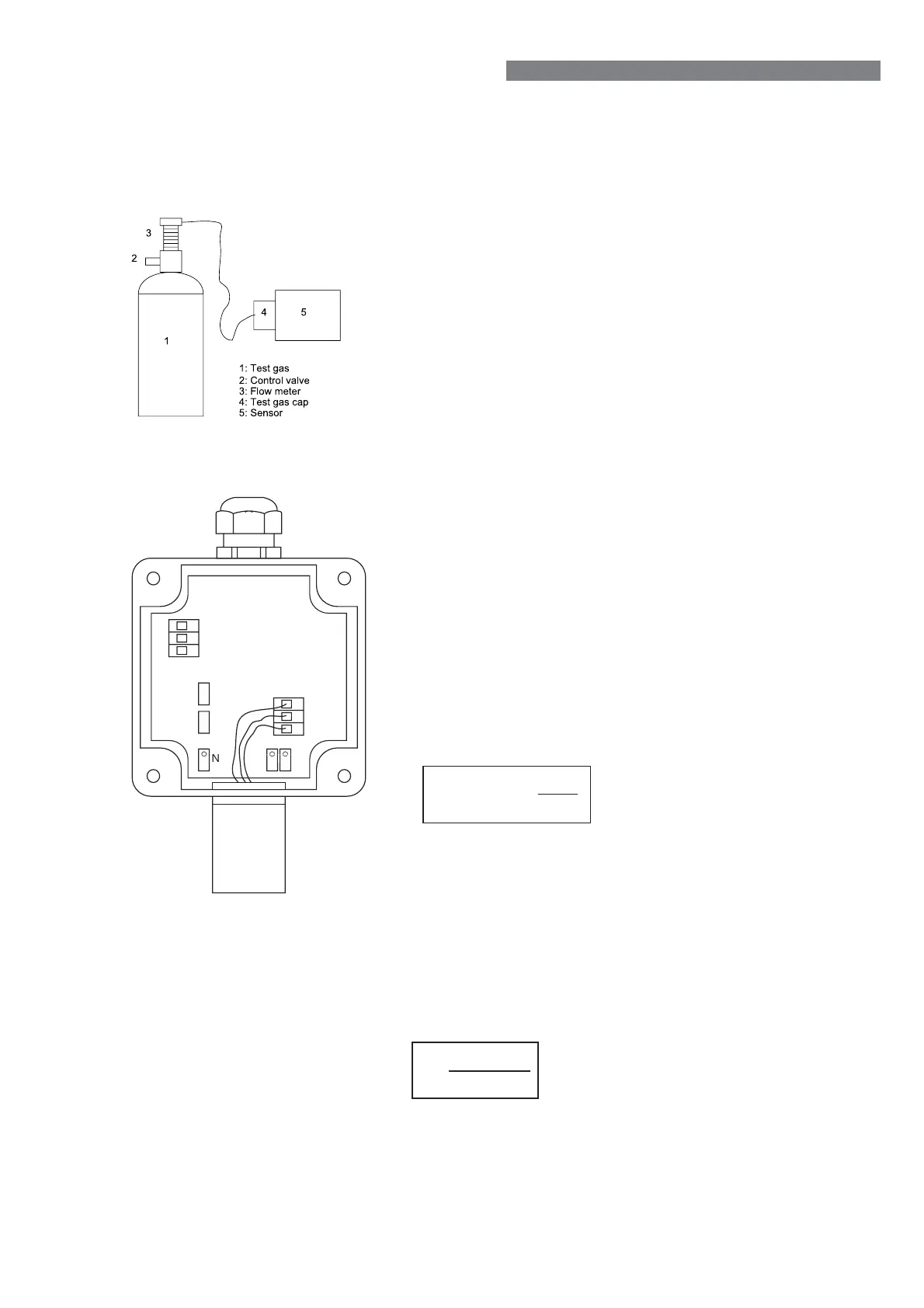
Setting the bridge voltage
● Apply zero-response gas (synthetic air) if the environment contains the gas
to be detected.
● Connect the voltmeter at the measurement socket „Br“.
● Wait for the voltage reading to stabilise.
● Adjust the „Br“ potentiometer until the voltmeter reads 0 mV.
Setting the base current to 4 mA
● Connect the voltmeter at the „0.4-2V“ socket.
● Wait for the „0.4-2V“ voltage signal to stabilise.
● Adjust the „N“ potentiometer until the voltmeter reading is 400 mV (4 mA).
Setting the 4-20 mA output current
● Apply test gas of a known concentration C1.
● Wait for the „0.4-2V“ voltage signal to stabilise.
● Adjust the „V“ potentiometer until the voltage corresponds to the value U
S
U = 0,4V +1,6V
s
C
C
max
1
C = testgas concentration in % LEL
1
max
C = Measuring range (100%LEL)
U = Signal voltage
s
24VDC
4-20 mA
GND
0,4-2V
Br
4
5
6
1
2
3
Measuring the sensitivity (bridge voltage)
● Connect the voltmeter at the measurement socket „Br“.
● Note the voltage reading U
Br
in mV.
● Remove the test gas.
● Write a test report.
Testing sensor sensitivity E:
● Calculate E using the following formula:
U
BR
= bridge voltage
C
1
= known test gas concentration
● If sensor sensitivity E < 0.5, the sensor must be replaced.
● If sensor sensitivity E is below 50% of the E value from initial adjustment
(works calibration), the sensor also must be replaced.
E =
U
BR
(mV)
C
1
(%UEG)