Do you have a question about the Big Dutchman 307pro and is the answer not in the manual?
Guide for installing the 307pro climate computer alongside the 378 unit.
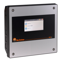
Instructions for positioning and securing the 307pro climate computer unit.
Guidance on installing an auxiliary contactor next to the climate computer.
Instructions for mounting the 24V power supply, either in a box or on a circuit board.
Information regarding the installation of the emergency opening system.
Guidelines for placing and installing climate sensors inside and outside the house.
Steps for connecting electrical components and ensuring safety compliance.
How to connect backup units for power failure compensation.
Procedure to set the computer's mains voltage to match the local supply.
Connecting additional 24V power supplies for greater power consumption needs.
Method for connecting multiple I/O modules, including cable requirements.
Configuring component connections using the computer's installation menu.
Setting jumpers on modules for specific functions like ON/OFF or input types.
Saving and printing installation setup configurations using the PC simulator.
Assigning unique CAN addresses to modules for communication.
Configuration steps for winch motors, including relay module and override switch settings.
Correctly setting CAN termination jumpers for reliable bus communication.
Information on symbols, letter codes, and reference designations used in diagrams.
Alphabetic codes for wire colours used in diagrams and markings.
A practical example showing the connection of a winch motor to the house computer.
Protecting relays by using protective diodes for DC supplied coils.
Diagrams showing the layout of connection terminals for various modules.
Wiring diagrams for various climate system configurations.
Diagrams illustrating cable connections for various winch motor models.
Tables specifying cable cross-sections based on length for 24V DC connections.
Wiring diagrams for MultiStep® systems with internal or external speed control.
Wiring diagram for Dynamic MultiStep® systems, including LPC functionality.
Wiring diagrams for three-phase and one-phase fan units.
Wiring for various climate control components including fans, heating, cooling, and sensors.
Circuit diagrams showing mains voltage distribution to I/O and Main modules.
Circuit diagram illustrating the connection of the alarm system.
Circuit diagrams for various emergency opening system configurations.
Circuit diagrams for internal speed control, including two parallel fans.
Wiring for single-phase and three-phase stir fans and wall fans.
Circuit diagrams for external speed controllers like MC 31 and MC 37.
Wiring diagrams for motor controllers like CL 600 LPC.
Wiring for combined motor systems like CL 600 LPC/CL 74CO and MultiStep®.
Detailed wiring diagrams for various winch motor models and positions.
Circuit diagrams for 0-10V analogue and relay-controlled room/floor heating systems.
Wiring for 24V and 230V blow heaters and stir fans.
Wiring diagrams for the Earny system, including distribution board connections.
Wiring diagrams for various sensors like DOL 12, DOL 114, CO2, and pressure sensors.
Diagrams for specialized connections like cooling, humidification, and soaking.
Details on connecting MultiStep® air outlets and recirculation fans.
Details on connecting stepless air outlets and recirculation fans.
Wiring for production system components: water meter, clock, light control, dimmer, and sensor.
Wiring diagrams for water meter and 24-hour clock functions.
Wiring diagrams for light relay, inspection light, dimmer, and light sensor.
Diagrams illustrating the connection of the delivery key and a relay.
| Brand | Big Dutchman |
|---|---|
| Model | 307pro |
| Category | Computer Hardware |
| Language | English |