EasyManua.ls Logo

Big Joe J1 - User Manual

Big Joe J1
24 pages
Print Icon
To Next Page IconTo Next Page
Loading...
OPERATOR’S MANUAL
Big Lift LLC
www.bigjoeforklifts.com
Manual Part No. 901628
05/15/2020
J1
TASK SUPPORT
VEHICLE
U.S. Patent Nos. D730,614; D733,389; D733,390; 9,440,830
and D734,589 Other patents pending
NOTE:This vehicle is for indoor and level surface use only.
NOTE: For the most current parts information and service updates, please
refer to the Big Joe Support site at www.bigjoesupport.com
Question and Answer IconNeed help?

Do you have a question about the Big Joe J1 and is the answer not in the manual?

Summary

General Safety Warnings

Proposition 65 Warning

Foreword

Safety Symbols

General Description of J1 Vehicle

Name Plate and Warning Decals

Before Operation

Pre-Operation Checks and Initial Use

Vehicle preparation steps and guidelines for initial operation to ensure safety and proper function.

Vehicle Controls Overview

Instrument Panel

Instrument Panel Displays and Indicators

Explanation of battery status, warnings, speed, and operating mode indicators on the instrument panel.

Operation

Safety Regulations and Driving

Operator responsibilities, safety rules, and basic driving procedures for the vehicle.

Stopping, Lifting, and Loading

Procedures for stopping the vehicle, raising/lowering the platform, and picking up loads safely.

Transporting, Parking, and Maintenance

Guidelines for transporting loads, parking, and safety during overhead maintenance.

Battery Maintenance

Battery Handling Safety

Safety precautions for handling and working with acid batteries, including fire protection.

Charging the Battery

Step-by-step instructions for safely charging the vehicle's battery.

Lubrication

Obtaining Parts and Service Manual

Overview

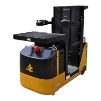
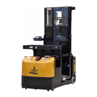
The Big Joe J1 Task Support Vehicle is a self-propelled, battery-powered elevating work platform designed for indoor use on level surfaces. It is intended for general maintenance work and efficient material handling in warehouses and storerooms, allowing a single operator to perform tasks such as stock selection, driving, and stock replacement at various heights.

Function Description:

The J1 vehicle lifts and transports an operator and loads up to 1,000 pounds (including the load shelf and occupant). It features an AC drive motor for forward and reverse propulsion, with speed restrictions when the platform is raised. On-demand power steering provides high maneuverability and quiet operation. The operator platform includes a "deadman" footswitch that must be engaged for the vehicle to operate. Control arms are used for vehicle operation and operator safety. A pick tray is provided for placing and transporting merchandise, and a folding rear tray can transport up to a 200-pound load.

Important Technical Specifications:

  • Capacity: Up to 1,000 pounds (including load and operator).
  • Rear Tray Capacity: Up to 200 pounds.
  • Voltage: 24V (individual battery voltage: 6V).
  • Vehicle Type: UL583 E.
  • Patents: U.S. Patent Nos. D730,614; D733,389; D733,390; 9,440,830; D734,589. Other patents pending.
  • Compliance: Designed and constructed in compliance with ANSI/SIA A92.6, OSHA, and CSA-B354.2-01 standards.
  • Operating Environment: Indoor and level surface use only. Not for use on mezzanines, balcony areas, ramps, slopes, or uneven floors.

Usage Features:

  • Operator Platform: Designed for a single operator, with a "deadman" footswitch for activation.
  • Controls:
    • Lift Button: Raises the platform when held, requires guard rails to be lowered and footswitch engaged.
    • Lower Button: Lowers the platform when held, requires guard rails to be lowered and footswitch engaged.
    • Horn Button: Sounds the horn.
    • Keyswitch: Two positions (ON/OFF); key removal prevents unauthorized use.
    • Travel Switch: Controls forward, neutral, and reverse travel; direction indicated on the instrument panel.
    • Emergency Power Disconnect Switch: Disconnects main power, deactivates electrical functions, and applies brakes automatically.
    • Steering Control: Conventional steering, drive wheel direction indicated on the instrument panel.
    • Battery Disconnect: Cuts off all power and connects batteries to the charger.
    • Emergency Lowering Button: Lowers the platform in emergencies.
  • Instrument Panel Displays:
    • Low Battery Alarm LED: Lights when battery voltage is 40% or less of nominal.
    • Fault Alarm LED: Lights when a fault is detected, with details on the display.
    • Temperature Alarm LED: Illuminates if the drive motor temperature is too high.
    • Drive Pedal Alarm LED: Illuminates when the drive pedal is released.
    • Brake Alarm LED: Illuminates when the brake is actuated.
    • Function Keys: Used to adjust speed mode (four ranges, "1" slowest to "4" highest) and switch driving mode (normal or crawl speed).
    • Battery Indicator: Ten notches display state of charge (each notch 10%).
    • Information Display: Shows warnings and faults.
    • Speed Display: Indicates vehicle speed.
    • Hour Meter Display: Shows total operating hours.
    • Speed Mode Display: Indicates selected speed range.
    • Steering Display: Nine notches indicate drive wheel steering angle.
    • Driving Mode Display: Shows normal or crawl speed. Crawl speed automatically engages when the platform reaches the speed limit switch, indicated by a "Turtle" icon.
  • Safety Features:
    • Guardrail access gates must be in place and lowered before elevating the platform.
    • Level sensor sounds an alarm if the vehicle is elevated on a slope greater than 4.5 degrees.
    • Speed is restricted when the platform is raised above a preset limit.
    • Brakes actuate when the emergency power disconnect switch is depressed.
    • Vehicle operation is disabled when control arms and guard rails are raised.
  • Operating Procedures:
    • Daily operator checklist required before use.
    • Always transport loads with the platform completely lowered.
    • Loads must be centered and within capacity ratings.
    • Avoid sudden stops, starts, or turns.
    • Maintain clear view and safe distance from obstacles.
    • Enter and exit platform only through raised access gates with the platform fully lowered and vehicle stopped.
    • Remove key when leaving vehicle unattended.

Maintenance Features:

  • Daily Operator Checklist: Includes checks for transmission, hydraulic systems, pick tray, rear tray, chains, cables, hoses, control arms, guard rails, safety labels, nameplate, horn, flashing lights, steering, travel controls, wheels, hydraulic controls, emergency brake switch, battery disconnect, high speed limit switch, and platform operation.
  • Periodic Maintenance: Requires a qualified service technician for lubrication, fluid levels, brake maintenance, motor maintenance, and other specified areas.
  • Hydraulic Oil: Check level, refer to page 22 for details.
  • Battery Maintenance:
    • Charge batteries as per instructions (page 21).
    • Battery cell covers, terminals, and connections must be clean and secure.
    • Non-insulated terminals must be covered with a non-slip insulation mat.
    • Refer to Supplement 245 for battery safety and maintenance.
    • Refer to Supplement 374 for charging instructions.
  • Lubrication:
    • Mast: Spray lubricant (Polylub GA352P) on the full length of the channel where rollers operate.
    • Hydraulic Reservoir: Fill with hydraulic oil (L-HM46#) to the level on the dipstick when the platform is fully lowered.
  • Parts and Service Manual: A complete manual is available from Big Lift LLC or www.bigjoesupport.com.

Safety Warnings:

  • Do not operate unless authorized, trained, and familiar with all warnings and instructions.
  • Do not modify the vehicle without manufacturer's consent.
  • Do not replace critical components (e.g., batteries) with lighter weight alternatives.
  • Do not exceed capacity ratings on the nameplate.
  • Do not stabilize the platform by contact with adjacent objects.
  • Do not use ladders, planks, or other devices to achieve additional height.
  • Do not leave the platform cage floor area while elevated.
  • Do not lean out from the outside of a cage rail or climb onto guard rails/trays.
  • Only one person permitted in the operator's compartment.
  • Wear eye protection, rubber overshoes, protective wear, and rubber gloves when servicing batteries.
  • Avoid smoking and open flames near batteries; ensure good ventilation and fire protection equipment.
  • Report any damage or unsafe conditions immediately and do not operate until corrected by a qualified service technician.
  • Do not make unauthorized repairs or adjustments.
  • Do not park on slopes; platform must be completely lowered.
  • Do not attempt to move a disabled vehicle; notify supervisor.

Big Joe J1 Specifications

General IconGeneral
BrandBig Joe
ModelJ1
CategoryUtility Vehicle
LanguageEnglish

Related product manuals