created: 04.16.19 E4-WM5-Y630A00_2 Page 3 of 22 latest revision: 09.29.20
B8 8100 bypass shock installation procedure:
B8 8100 bypass shocks are corner specific. The step by step procedure is shown with pictures of the right side,
and in some cases, pictures of the left. See pages 20 and 21 for the end result.
A.
Remove the existing shock from the vehicle following all procedures in the vehicle manufacturer’s service manual.
Inspect the OE lower shock bolt/washer for any damage or excessive wear. If these components are in good
condition, save them for reuse later. If damage or excessive wear is present on any of these components, purchase
the required replacement OE components.
B.
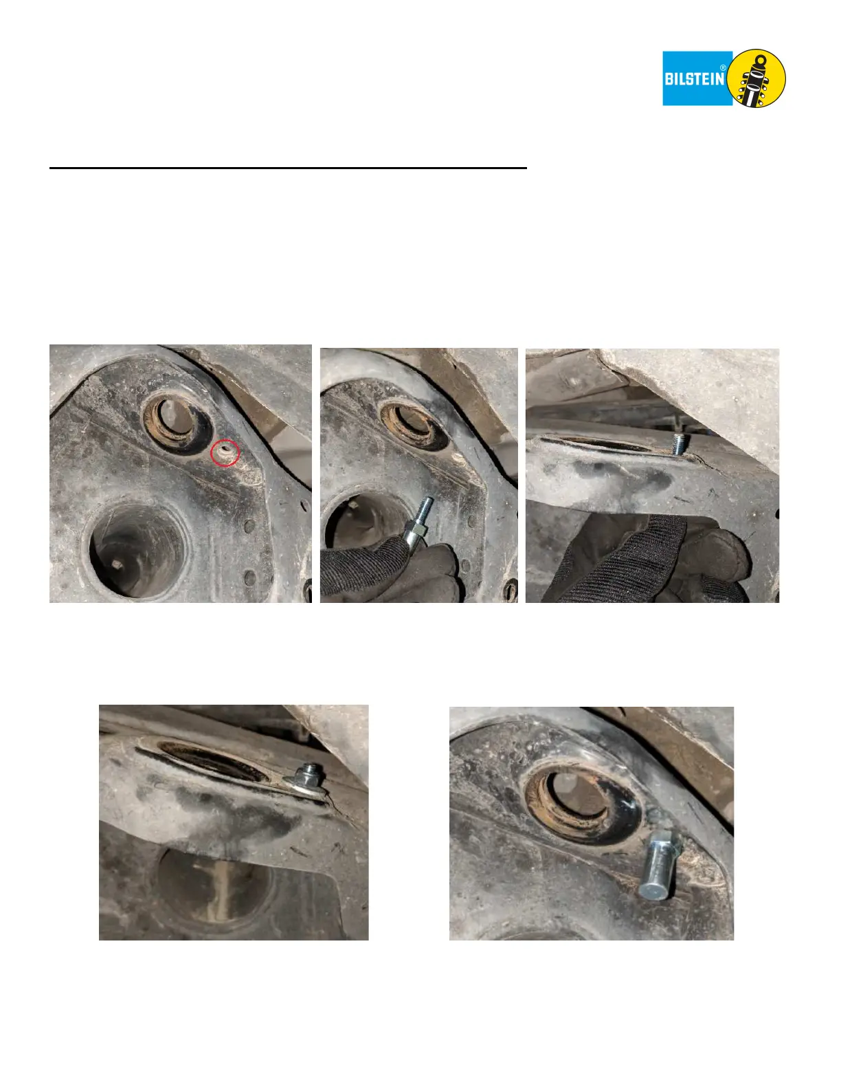
Place the Anti Rotation Pin (BOM item #1) into the frame hole circled in red below. This hole is towards the front of the
shock mount hole.
Right side depicted. Left side is a mirror image.
C.
Hold the Anti Rotation Pin with a ½” or 13mm deep socket. Place a Washer (BOM item #2) over the threaded stem
from the top side of the frame. Thread the Nylock (BOM item #3) onto the stem. Then, hold the Anti Rotation Pin
assembly towards the rear of the vehicle and tighten the Nylock with a 10mm ratcheting wrench.
Torque the Nylock to 7 ft-lb (10 Nm).
Right side depicted. Left side is a mirror image.
 Loading...