10
LVP180914 Rev. D
www.bindicator.com
For STANDARD models, skip to Step 16; for ADVANCED models continue to Step 12.
Auxiliary Relay Connections - ADVANCED MODEL ONLY
12. Refer to Figures 9 and 7 when connecting to the auxiliary relay.
13. Pull approximately 2.5” (6.35 cm) of cable through conduit and strip
1
/
4
” (6 to 7 mm).
14. Attach leads to terminal block as shown in Figure 7. (2.0 in-lb, 0.23 N-m)
15. Check that all wires are held tightly in place by lightly pulling each conductor.
Remote Rod Connections
16. Refer to Figure 10 when connecting the remote rod.
17. Pull approximately 2.5” (6.35 cm) of cable through conduit and strip
3
/
16
” (4 to 5 mm).
18. Connect factory supplied cable to terminal board as shown in Figure 10.
19. Check that all wires are held tightly in place by lightly pulling each conductor.
20. Replace cover and tighten set screw to lock cover in place.
21. Loosen the remote housing cover screws and remove cover.
22. Pull approximately 4” (10.16 cm) of cable through conduit and strip
3
/
16
” (4 to 5 mm).
23. Connect factory supplied cable to terminal board as shown in Figure 10.
24. Check that all wires are held tightly in place by lightly pulling each conductor.
25. Reinstall the gasket, if necessary.
26. Replace cover and tighten screws to 60 in-lb (6.8 N-m) of torque.
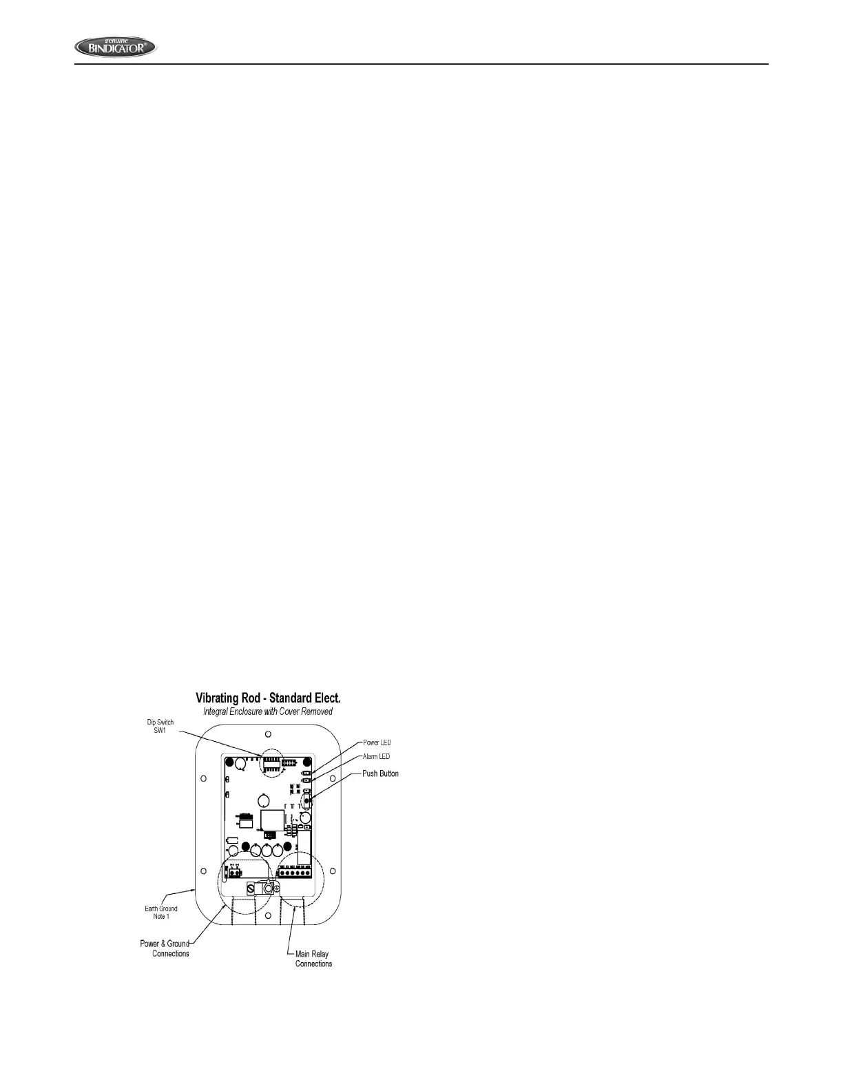
Figure 3. LP II Integral Enclosure with Cover Removed - STANDARD
Note:
1. For safety, properly ground the
enclosure to an adequate earth
ground.