User's Manual • 3-9
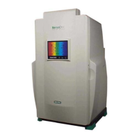
Figure 3.7a Figure 3.7b
Figure 3.7c
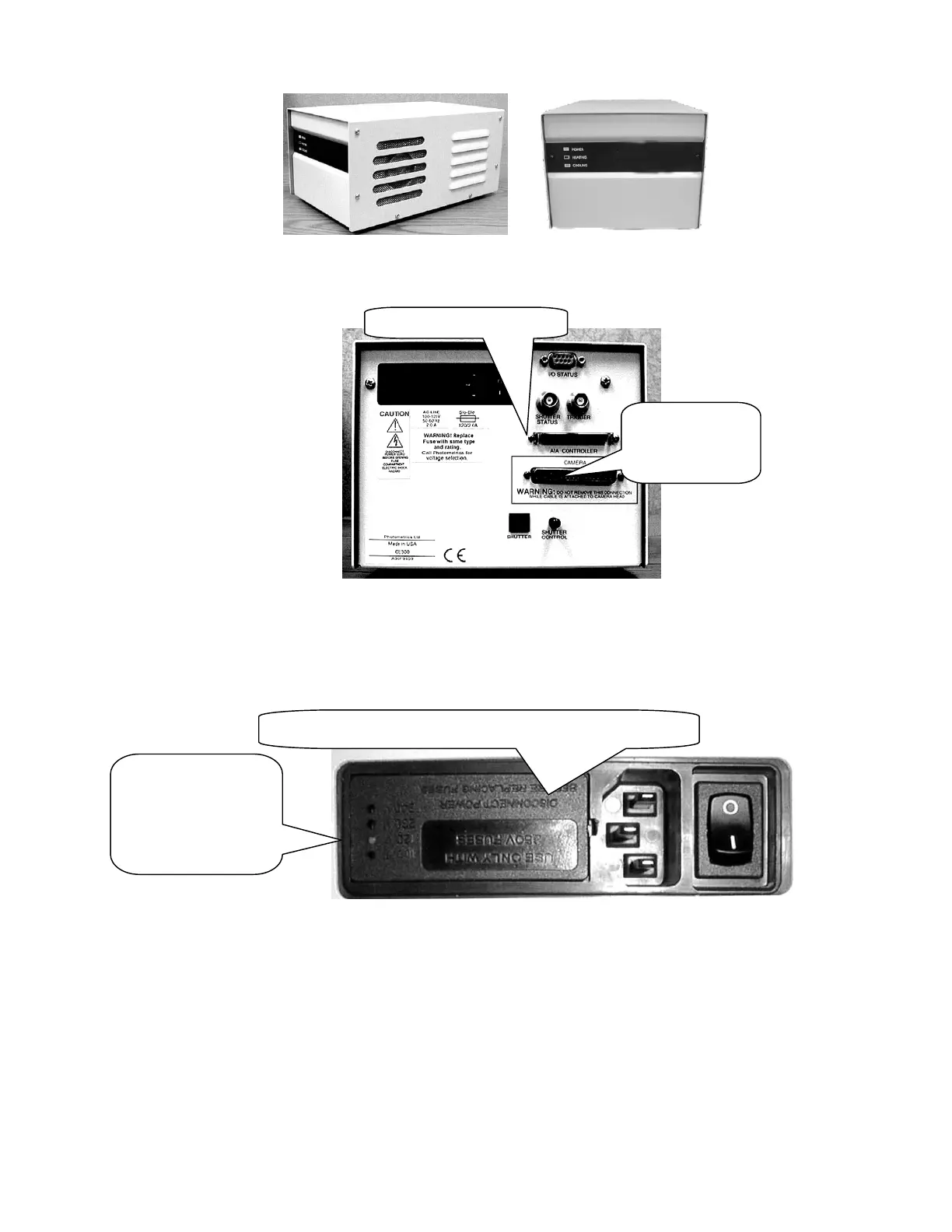
2. A small white tab on the AC inlet located on the rear panel indicates the voltage
setting on your camera controller unit. See Figure 3.8
Figure 3.8
3. Pull out the small tab near the AC inlet using a small screwdriver. See Figure 3.8
4. The TAB holds a fuse completely remove it. This will expose a tiny PCB located in a
tiny slot as shown in Figure 3.9
White plastic stub
shows the current
voltage setting.
Make sure it
matches with the
local voltage.
Insert a small screw driver and pull out the tab
AIA Connector on CEU
Camera
Controller Cable
Connector