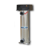
BIO-UV
Copyright BIO-UV 03/07/08
8
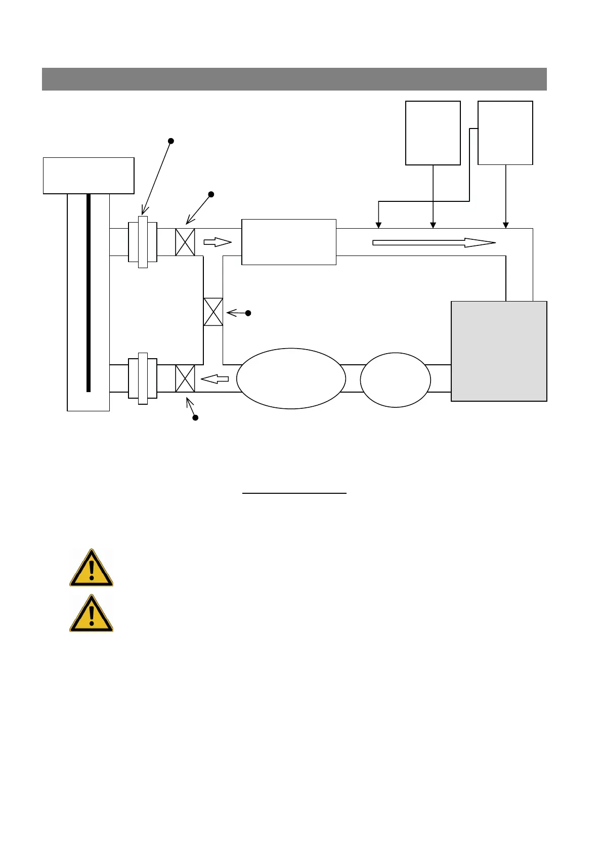
Standard Installation
RECOMMANDATIONS
Install the BIO-UV equipment in the equipment room, respecting the 0.1 and 2 safety areas around the
volume in accordance with the current installation rules (NF C15100)
Unless the equipment is dismantled in order to change the lamps and clean the quartz sleeves,
leave enough room to remove the lamps – the AVAILABLE HEIGHT in the equipment
room must be DOUBLE the total size of the equipment
The BIO-UV equipment must be installed on the discharges after the filter and before the
heater (where applicable).
The equipment’s water inlet should preferably be at the bottom and, thus, its outlet to the pool at the top.
(If necessary it can be positioned horizontally).
The unions provided for ease of fitting and dismantling are supplied with either a 50 mm (UV10 & 20),
63 mm (UV30) or 75 mm diameter (UV40).
If a bypass is used for the heating, the BIO-UV equipment should be installed before the bypass
Using clamping collars (50, 63 or 75 mm diameter
) secure the REMANENT and pH liquid injectors and pH
analysis probe in the correct order, see diagram above.
BIO-UV
DOSING
PUMP
INJECTION
BIO-UV
pH
REGULAT
OR
BY-PASS VALVE
BY-PASS VALVE
BY-PASS VALVE
Ø50 ou 63 ou 75 UNION
PROBE
HEATING
FILTRE
SWIMMIN
G POOL
PUMP
BIO-UV