Relay response to malfunctions (see chapter 6 Troubleshooting):
General
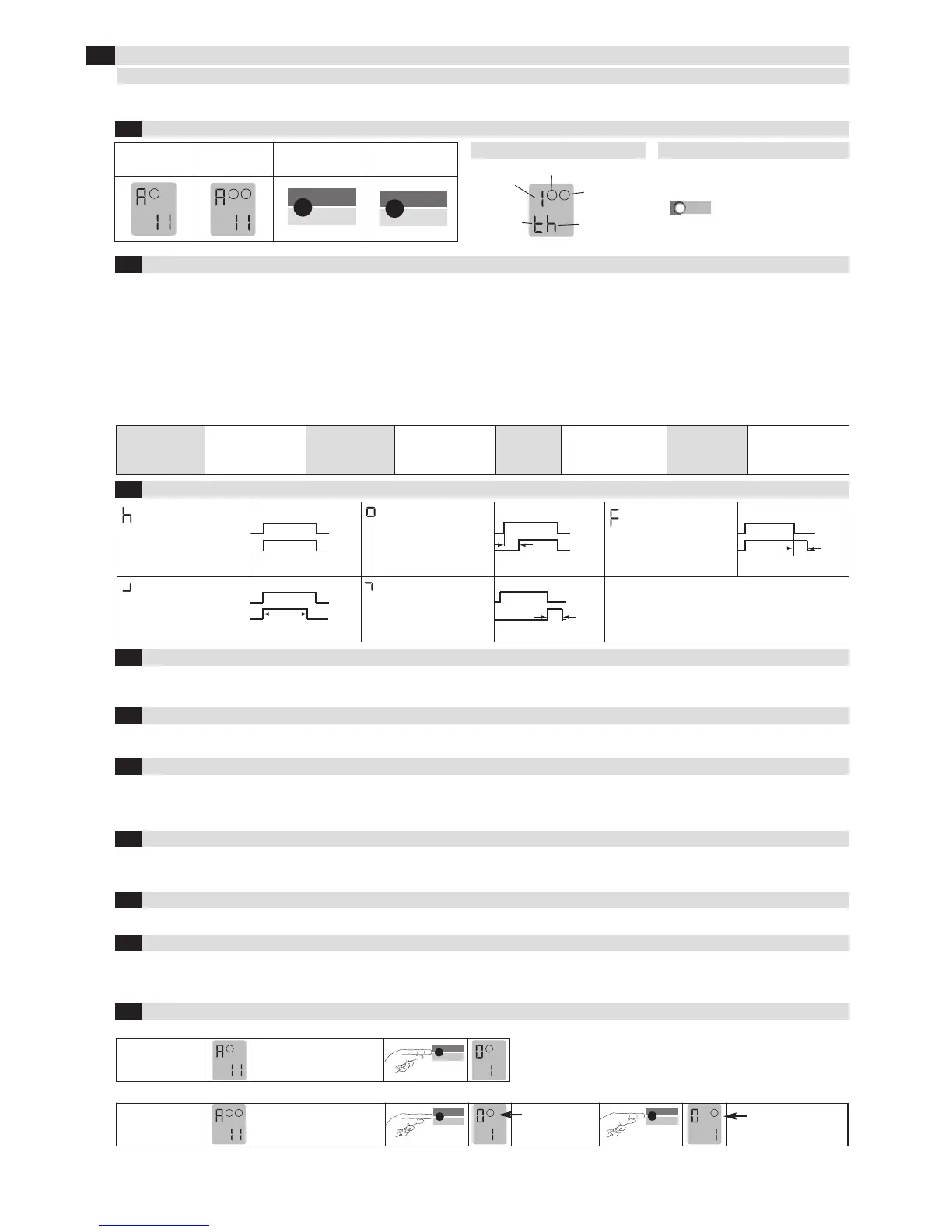
Explanation of the LCD display
Explanation of the LED
Standard display
1-loop device
Standard display
2-loop device
Control button Control button
Loop 2,
output 2
Example:
Parameter «h»
set
Function
Example:
Time
function set
Loop 1, output 1
Red & green: Start-up phase
Green: Operation
Red & green: Configuration
Flashing green: Loop activated
Flashing red: Error
Flashing
red + green: Simulation
The settings of the ProLoop devices in this chapter are shown and explained for the 1-loop device. The settings for loop 2 of a 2-loop device should be
made using the corresponding method.
The relay picks up when the
loop is activated and drops
out when the loop is exited.
On delay:
The relay picks up after the
time t when the loop is acti-
vated and drops out when
the loop is exited.
Off delay:
The relay picks up when the
loop is activated and drops
out after the time t when the
loop is exited.
Activation pulse:
The relay picks up when the
loop is activated and drops
out again after the time t.
Impulse by leaving the loop:
By leaving the loop,
the relay picks up after
the time t, relay drops out.
1.Door/gate
systems
A malfunction causes
the output relay to be
released. The alarm
relay drops out.
2. Barrier
A malfunction causes
the output relay to pick
up. The alarm relay
drops out.
3. Quiescent
current
A malfunction causes the
output relay to be
released. The alarm relay
drops out.
4. Direction logic
(2-loop device
only)
A malfunction causes
the output relays to be
released. The alarm
relay drops out.
Parameters
1: Door and gate The assigned output relay picks up when the loop is activated and drops out when the loop returns to a non-activated condition.
2: Barrier The assigned output relay picks up when the loop is activated and drops out when the loop returns to a non-activated condition.
3: Quiescent current The assigned output relay drops out when the loop is activated and picks up again when the loop returns to a non-activated condition.
4: Direction logic Output 1 switches if an object moves from loop 1 to 2. Output 2 switches if an object moves from loop 1 to 2. Both loops must be
activated for a short time. The outputs are reset again when loop 2 returns to a non-activated condition. Both loops must have re-
t
urned to a non-activated condition for another direction detection.
0: Loop 2 Loop 2 can be deactivated in a 2-loop device.
The sensitivity 5 (=Sensitivity) of the loop detector can be adapted in 9 stages: 51 = Lowest sensitivity, 59 = Highest sensitivity,
56 = Factory setting. The sensitivity setting depends on the frequencies (see chapter 4.6 Frequency).
In a device with 2 outputs, output 2 can be either activated or deactivated. In ProLoop 11, output 2 can also be set as an alarm output.
Four different frequencies F1, F2, F3, F4* can be set in order to avoid interference when using several loop detectors. These settings influence the
sensitivity (the sensitivity can be set in the range 1–7 for frequencies F1 to F3). F2 to F4 can be set for inductance < 150 µH and only F4 can be set for
inductance < 75 µH.
The direction logic function can only be used with a 2-loop device. Direction logic must have been set in the basic function (see chapter 4.2). Detection
can be performed from: ➝ Loop 1 to loop 2 ➝ From loop 2 to loop 1 ➝ from both directions
Display after start-up:
Touch the «Mode» button once
to change to configuration
mode
Touch the «Mode» button once
to change to configuration
mode
*Factory setting
Loop 2 is
selected
Loop 1 is
selected
ASB (=Automatic Sensitivity Boost). ASB is required in order to be able to recognise trailer drawbars after activation.
Basic function 2 «Barrier systems» must be set for this function. This function is inactive by default (= factory setting).
P 1 = Car parks and automatic parking bollards: The sensitivity is restricted to 1–5 and the time function to h.
4
V
alue and parameter setting options
LCD display and controls
4
.1
Basic functions 0 (see Table 4.11a for settings)
4.2
Time functions 1, time unit 2 and time factor 3 (see Table 4.11a for settings)
4.3
Sensitivity 4 (see Table 4.11a for settings)
4.4
Automatic Sensitivity Boost ASB 5 (see Table 4.11a for settings)
4.5
Frequency 6 (see Table 4.11a for settings)
4.6
Direction logic7 (see Table 4.11a for settings)
4.7
Output 2 8 (see Table 4.11b for settings)
4.8
Protection against power failure 9 (see Table 4.11a for settings)
4.9
Changeover from operation to configuration mode
4.10
1- loop device
2- loop device
2
 Loading...