Return to function mode
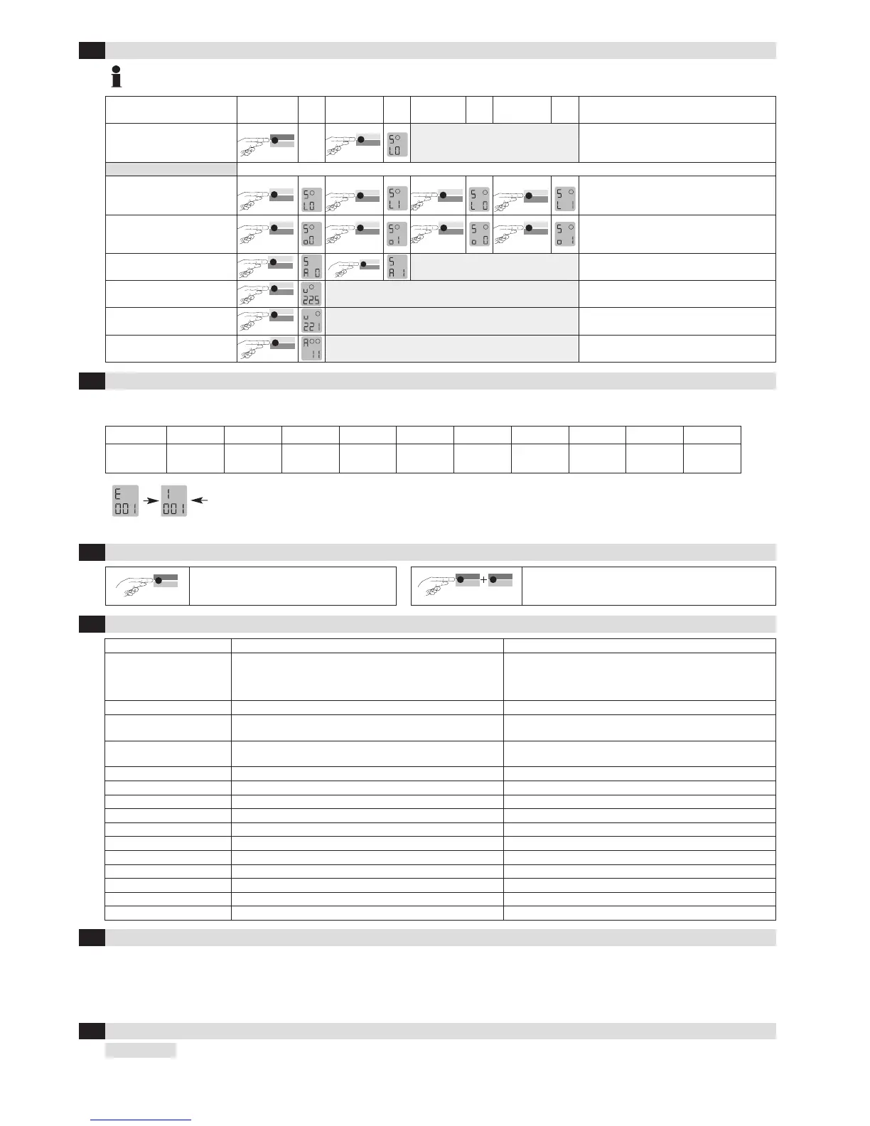
The activation of the loops can only be simulated if loops are connected to the appropriate terminal!
The displays apply similarly for loop 2
If an error occurs, operating mode «A» and error display «E» light up alternately and an error code such as E 012 is displayed. The LED changes to flashing
red, the 4 most recent errors are stored and can be interrogated.
Display E001 E002 E011 E012 E101 E201 E301 E302 E311 E312
Error
Interruption
Loop 1
Interruption
Loop 2
Short circuit
Loop 1
Short circuit
Loop 2
Under-
voltage
EPROM
Error
Loop 1
too large
Loop 2
too large
Loop 1
too small
Loop 2
too small
Briefly pressing the «Data» button shows the last of 4 errors on the display. Another short press switches to the error before that,
and so on. When the button is pressed for the 5th time, the device switches back to automatic mode. If you press the «Data» button
for 2 seconds during the query, all error messages are deleted. The figure shows memory slot 1 in which error 001 Interruption loop
1 has been stored (example).
ProLoop ProLoop 11
Supply voltage /
Power consumption
24 VAC –20 % to +10%, max. 2 VA
24 VDC –10% to +20%, max. 1.5 W
94–240 VAC ± 10%, 50/60, max. 2.9 VA
24 VAC –20% to +10%, max. 1.8 VA
24 VDC –10% to +20%, max. 1.3 W
115 VAC –15% to +10%, max. 3.5 VA
230 VAC –15% to +10%, max. 3.7 VA
Power consumption
max. 2 VA 24V 1.2 VA
Loop inductance
max. 40–1000 µH,
ideally 80–300 µH
max. 40–1000 µH,
ideally 80–300 µH
Loop connection wiring
max. 200 m 1,5 mm
2
min. 20x/m
max. 200 m 1,5 mm
2
min. twisted 20x/m
Loop resistance
< 8 Ohm with connection wire < 8 Ohm with connection wire
Output relay (loop)
240 VAC/2 A AC1 240 VAC/2 A AC1
Output relay (alarm)
60 VAC, 0.3 A, AC1 –
Dimensions
22.5 x 94 x 88 mm (W x H x D) 36 x 74 x 88 mm (W x H x D)
Housing mounting
Direct DIN rail mounting Mounting rail installation via 11-pin base ES 12
Connection type
Plug-in terminals Screw terminals base ES 12
Protection class
IP 30
IP 20
Approvals, safety
See declaration of conformity at www.bircher-reglomat.com See declaration of conformity at www.bircher-reglomat.com
Operating temperature
–20°C to +60°C –20°C to +60°C
Storage temperature
–40°C to +70°C –40°C to +70°C
Air humidity
<95% non-condensing <95% non-condensing
Manufacturer: Bircher Reglomat AG, Wiesengasse 20, CH-8222 Beringen declares that the
Product, type: ProLoop, ProLoop 11
Model: 24VDACDC, 115VAC, 230VAC, 1-loop devices, 2-loop devices
Intended purpose: Programmable loop detector for controlling gates and barriers as well as for regulating and counting cars in parking areas
if used in accordance with the intended purpose, complies with the basic requirements acc. to:
R&TTE Directive, Appendix III 1999/5/EC
2
6
3
6
7
7
F
0
6
/
1
0
5
S
imulation mode
6
Troubleshooting
7
Reset
8
Most important technical data
9
Declaration of conformity
10
Contact data
 Loading...