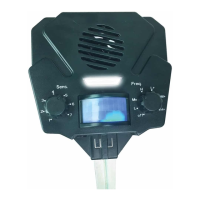
5) Turn the power switch (located in the upper right
hand corner of the faceplate) to INT/EXT. SPKR (ON
position). (NOTE: The unit may take a couple of
seconds before starting).
6) Adjust the volume to the desired level.
7)
After turning the unit OFF, be certain to wait AT
LEAST 60 SECONDS before turning it back on.
8) Close the cover and latch shut. Ensure that the
cover is properly latched closed and do not open
the cover during rain or other conditions that would
expose the inside of the control unit to water.
PROGRAMMING YOUR BIRDXPELLER
To program your
BirdXPeller PRO unit you
will need a small screw-
driver, toothpick, or other
pointed, rigid object to
move the switches in the
switch array (see FIG.
1). The switch arrays
are the switch banks
located in the bottom right-hand corner on the
faceplate (inside the clear front cover). A switch
is ON if the switch is moved to the right-hand
side. The switch is OFF if the switch is moved
to the left-hand side.
BIRD RECORDING SETTING SWITCHES
The Bird Recording
Switches are the first
eight switches (FIG. 2)
in Switch Array #1. Each
switch has a recording
number to the left of it
that corresponds with the
bird descriptions listed
on the foil label inside the cover on the front the
unit, they are as follows:
For best results, choose a combination of both
predator calls AND bird distress recordings to
create the most natural scenario.
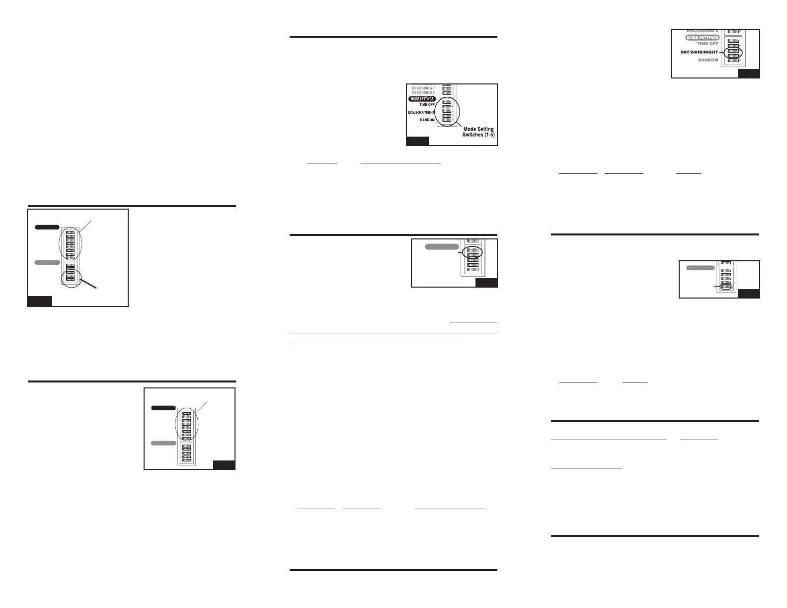
MODE SETTING SWITCHES
The Mode Setting Switches are the last five
switches (FIG. 3) in Switch Array #2. These
set the various modes of operation: such as the
amount of time between playing bird distress
calls, when the unit will
operate (day only, night
only, or 24-hours), and
whether the unit will
operate in the random
mode or normal mode.
Switch Mode or Function
1 Sets the Time-Off Period
2 Sets the Time-Off Period
3 Sets the Time the unit plays
4 Sets the Time the unit plays
5 Turns Random Mode On or Off
DELAY SWITCHES
The two "Delay" or Time-
Off Switches are
located
just below the Recording
Switches (1-8) in the switch
array (FIG. 4). The unit will
delay a number of seconds or minutes between
recorded sounds when the unit is set to one
of the various Time-Off Modes. The TEST
setting is appropriate for testing, but is NOT
recommended for long-term success. Please
note that the unit will play all of the selected
recordings (either sequentially or non-sequentially,
depending on the Random Mode), then it will go
into a delay. The time the unit stays off depends
on the Time-Off and the Random Mode Settings.
If the unit is operating in Random Mode, the unit
will delay anywhere from the minimum value to
the maximum value for that Time-Off setting. If
the unit is not in Random Mode, it will delay only
the minimum value.
To set the Time-Off period (or delay interval), use
the following settings on switches
1 and 2 in the
Mode Function Settings.
Switch 1 Switch 2 Time Off Period
ON OFF Test (17-50 sec.)
OFF ON Medium (1-4 min.)
ON ON Long (5-10 min.)
OFF OFF X Long (10-30 min.)
TIME OF OPERATION SWITCHES
The two Time of Operation switches are located
just under the Time-Off
Switches in the switch
array (FIG. 5). The unit
will operate day only, night
only, or continuously (24-
hours). However, the photocell that senses the
sunlight is susceptible to bright lights. Take care
not to have bright lights shining toward the front
of the unit since this can prevent the unit from
operating properly. To set the time period for the
unit to operate set switches
3 and 4 in the Mode
Function settings to the following:
Switch 3 Switch 4 Mode
ON OFF Day Only
OFF ON
24-Hour
ON ON Night Only
OFF OFF Night Only
RANDOM OPERATION SWITCH
The Random Operation Switch is the bottom
switch in the switch array (FIG. 6). The unit will
randomly play the selected
recordings in non-sequential
order when operating in
Random Mode. When the
unit is not operating in the Random Mode, the unit
will play the selected recordings in a sequential
order. The Random Mode is recommended to
keep birds from adapting to a preset pattern of
sounds. To operate the unit in Random Mode, set
switch
5 as follows:
Switch 5 Mode
ON Random mode ON
OFF Random mode OFF
PROGRAMMING EXAMPLE
Bird Recording Switches: Results:
1, 3, 5 and 6 to “ON” position Plays Birds 1, 3, 5 & 6
Mode Switches:
1 = “OFF” position
2 = “ON” position (Medium), every 1 to 4 minutes
3 = “ON” position
4 = “OFF” position Operates during daylight hours only
5 = “ON” position In random, non-sequential order
VOLUME CONTROL
The unit has a volume control dial on the front
panel of the unit. Turning the dial toward LOW will
reduce sound output and rotating the dial toward
RECORDING 1
RECORDING 2
RECORDING 3
RECORDING 4
RECORDING 5
RECORDING 6
RECORDING 7
RECORDING 8
TIME OFF
DA
Y/24HR/NIGHT
RANDOM
1 2 3 4 5 6 7 8 1 2 3 4 5
RECORDING
Switches (1-8)
RECORDINGS
RECORDINGS
MODE SETTINGS
MODE
SETTING
Switches
(1-5)
FIG. 1
RECORDING 1
RECORDING 2
RECORDING 3
RECORDING 4
RECORDING 5
RECORDING 6
RECORDING 7
RECORDING 8
TIME OFF
DA
Y/24HR/NIGHT
RANDOM
1 2 3 4 5 6 7 8 1 2 3 4 5
RECORDING
Switches (1-8)
RECORDINGS
RECORDINGS
MODE SETTINGS
FIG. 2
1 Blackbird
2 Crow
3 Grackle
4 Cormorant
5 Raven
6 Bird Predator I
7 Bird Predator II
8 Bird Predator III
FIG. 3
RECORDING 1
RECORDING 2
RECORDING 3
RECORDING 4
RECORDING 5
RECORDING 6
RECORDING 7
RECORDING 8
TIME OFF
DA
Y/24HR/NIGHT
RANDOM
1 2 3 4 5 6 7 8 1 2 3 4 5
RECORDINGS
RECORDINGS
MODE SETTINGS
FIG. 4
FIG. 5
RECORDING 1
RECORDING 2
RECORDING 3
RECORDING 4
RECORDING 5
RECORDING 6
RECORDING 7
RECORDING 8
TIME OFF
DA
Y/24HR/NIGHT
RANDOM
1 2 3 4 5 6 7 8 1 2 3 4 5
RECORDINGS
RECORDINGS
MODE SETTINGS
FIG. 6
 Loading...