EasyManua.ls Logo

BIRD 428B-83H-01-M User Manual

BIRD 428B-83H-01-M
60 pages
To Next Page IconTo Next Page
Page #1 background imageLoading...
Page #1 background image
YOU'RE HEARD, LOUD AND CLEAR.
8625 Industrial Parkway, Angola, NY 14006 Tel: 716-549-4700 Fax: 716-549-4772 sales@birdrf.com www.bird-technologies.com
Installation and Operation Manual for
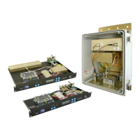
Compact Tower Top Amplifier System
Model 428B-83H-01-M/-48 and 428B-83H-01-C-110/48
and Model 428B-83H-01-T
Manual Part Number
7-9487

Table of Contents

Questions and Answers:

BIRD 428B-83H-01-M Specifications

General IconGeneral
BrandBIRD
Model428B-83H-01-M
CategoryAmplifier
LanguageEnglish

Summary

Warranty and Terms of Sale

Warranty Policy

Covers product defects, limitations, and warranty exclusions for one year from shipment.

Terms and Conditions of Sale

Details pricing, payment, shipping, claims, and return policies.

Safety and Operational Symbols

Hazard Warnings

Symbols indicating potential dangers such as high voltage, electrical shock, hot surfaces, and heavy lifting.

System Overview

Tower Top Box (TTA)

Describes the TTA unit, its function, and components.

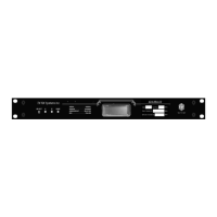
Base Control Unit

Details the ground-mounted unit housing alarms, power supply, and display.

Base Control Unit Details

Base Control Unit Overview

Describes the unit's function, components, and user interface access.

MCU and CMU Specifications

MCU TTA Functional Block Diagram

CMU TTA Functional Block Diagram

Pre-Installation Checkout

Initial Power-Up Test Procedure

Details the procedure for temporarily interconnecting and powering up the system for testing.

System Startup and Testing

Bench Testing Procedure

Outlines steps for verifying system component functionality and measuring sensitivity.

System Menu Navigation

System Installation and Testing

Installing the Tower Top Box

Step-by-step guide for mounting the tower top box and securing connections.

MCU System Grounding Guidelines

CMU System Grounding Guidelines

Grounding Requirements

Specifies grounding connections for surge protectors and the CMU ground stud.

Master Ground Buss Connection

Details the connection points and importance of the master ground buss.

System Installation Guideline Notes

System Optimization and Data Entry

System Optimization Overview

Discusses the stages of amplification and the need for adjustments for optimal performance.

Attenuation Settings and Adjustments

Reserve Gain Adjustment

Explains how to adjust reserve gain using manual or automatic modes via software.

Receiver Multicoupler Distribution (MCU Only)

Details adjusting distribution attenuation for optimal receiver multicoupler gain.

Reserve Gain Setting Procedures

Determining MCU Reserve Gain

Illustrates the calculation for MCU reserve gain using fixed and variable attenuation.

Setting CMU Reserve Gain

Explains how to set CMU reserve gain using TTA and GTR8000 attenuators.

Attenuator Adjustments

Reserve Gain Adjustment Procedure

Step-by-step guide for adjusting programmable attenuation for reserve gain.

System Adjustments and Analysis

Spectrum Analysis Overview

Explains the importance of spectrum analysis for receiver performance and sensitivity.

Spectrum Analysis

Procedure for Spectral Analysis

Steps to perform a spectral analysis to verify signals and gain adjustments.

Maximum Signal Level Mask

Operational Tests: Sensitivity and Degradation

Static System Sensitivity Measurement

Defines static sensitivity and how to measure it using the test port.

Measuring Static Sensitivity (Load Connected)

Step-by-step procedure for testing static sensitivity with the amplifier input loaded.

Effective System Sensitivity Measurement

Defines effective sensitivity and how to measure it with the antenna connected.

Sensitivity Measurement Calculations

Calculating Actual Sensitivity

Formula and example for calculating actual static and effective sensitivity.

Static Sensitivity Measurement with Load

Details the procedure for measuring static sensitivity with the amplifier input loaded.

Effective Sensitivity and Routine Operation

Measuring Effective Sensitivity (Antenna Connected)

Step-by-step procedure for measuring effective sensitivity with antenna connected.

Degradation Measurement Procedure

Explains how to determine system degradation by comparing static and effective sensitivity.

Amplifier Monitoring and Status

System Status Indicators and Alarms

System Alarm Conditions

Lists conditions that trigger system alarms, such as abnormal current or communication loss.

System Test Mode Operations

Test Mode Overview and Warnings

Explains how to use the test mode to select active amplifiers and control inputs.

System Troubleshooting Guide

Performance Degradation Analysis

Discusses common causes like sensitivity loss and interference, and troubleshooting steps.

Hardware Problem Identification

Identifies common hardware issues such as lightning strikes and vandalism.

Loss of Sensitivity Troubleshooting

A troubleshooting guide for intermittent and continuous loss of receiver sensitivity.

Maintenance and Troubleshooting

Lightning Protection and Arresters

Information on lightning arresters, their function, and potential failure modes.

Appendix A: Ethernet Connectivity

TTA Network Configuration Access

TTA Network Port Security

Telnet Security and Password Management

Appendix B: Changing Service Computer IP Address

IP Address and Subnet Mask Settings

Related product manuals