EasyManua.ls Logo

BIRD 428B-83H-01-T User Manual

Default Icon
60 pages
To Next Page IconTo Next Page
Page #1 background imageLoading...
Page #1 background image
YOU'RE HEARD, LOUD AND CLEAR.
8625 Industrial Parkway, Angola, NY 14006 Tel: 716-549-4700 Fax: 716-549-4772 sales@birdrf.com www.bird-technologies.com
Installation and Operation Manual for
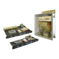
Compact Tower Top Amplifier System
Model 428B-83H-01-M/-48 and 428B-83H-01-C-110/48
and Model 428B-83H-01-T
Manual Part Number
7-9487

Table of Contents

Questions and Answers:

BIRD 428B-83H-01-T Specifications

General IconGeneral
BrandBIRD
Model428B-83H-01-T
CategoryAmplifier
LanguageEnglish

Summary

Warranty

Terms and Conditions of Sale

Outlines prices, terms, quotations, acceptance, shipping, claims, and modifications for product sales.

Symbols Commonly Used

Changes to this Manual

Contact Information

Lists phone numbers and email addresses for sales, customer service, and technical publications.

Appendixes

Appendix A: Front Panel Ethernet Connectivity

Details how to connect to the TTA system via Ethernet for control and monitoring using a web interface.

Appendix B: Changing Your Service Computers IP Address

Guides on modifying the service computer's IP address to ensure compatibility for TTA system connection.

General Description

Tower Top Box

Describes the TTA's tower-mounted component, detailing its integrated filtering and low-noise amplifier.

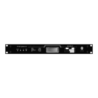
Base Control Unit

Describes the ground-mounted unit, including its power supply, display panel, and test port capabilities.

Base Control Unit Styles

Details the two available styles of base control units: MCU and CMU, and their differing functionalities.

MCU

Explains the MCU style base control unit, its multicoupler function, and expansion capabilities for multiple receivers.

Functional Block Diagram

Illustrates the system's functional block diagram, showing the signal path and component interconnections for the TTA and MCU.

Installation

Test Transmission Line

Explains the requirement and installation process for a dedicated test transmission line for system diagnostics.

Pre-Installation Checkout

Mechanical Inspection

Details the steps for performing a thorough mechanical inspection of the tower top box assemblies and connectors.

Initial Power-Up Test

Describes the procedure for conducting the initial power-up test using temporary cables at ground level.

Bench Testing

Explains how to verify system component functionality and measure sensitivity before tower mounting.

Optimizing the System

Feedline Data

Details how to determine and record main and test transmission line losses for system configuration.

Attenuation Settings

Discusses the use of programmable attenuators for optimizing reserve gain and receiver multicoupler distribution.

Reserve Gain

Defines reserve gain and explains how to adjust its programmable attenuator manually or automatically.

Setting the CMU Reserve Gain Attenuation

Explains how to adjust CMU reserve gain by configuring both GTR8000 and TTA attenuators.

Setting the MCU Reserve Gain Attenuation

Details the procedure to set MCU reserve gain attenuation to achieve a specific net gain level.

GTR8000 Attenuator Adjustment

Reserve Gain Adjustment Procedure

Provides step-by-step instructions to adjust the programmable attenuation for optimizing system reserve gain.

Setting Distribution Attenuation (MCU Only)

Spectrum Analysis

Procedure for Spectral Analysis

Outlines the steps to perform a spectral analysis to validate signal levels and reserve gain adjustments.

Operational Tests (Sensitivity and Degradation)

Front Panel Test Port

Explains the function and use of the front panel test port for performing static sensitivity tests.

Tower Top Amplifier Inputs

Describes the signal path for RF signals entering the tower top amplifier from the antenna.

Static System Sensitivity

Defines static sensitivity and the method for measuring it with the amplifier's internal load connected.

Measuring Static Sensitivity (Load Connected)

Provides detailed steps to test static system sensitivity by connecting the amplifier's input to the internal load.

Effective System Sensitivity

Measuring Effective Sensitivity (Antenna Connected)

Details the steps for testing effective system sensitivity with the antenna connected to the amplifiers.

Degradation

Explains how to calculate system degradation by comparing static and effective sensitivity measurements.

Routine Operation

Amplifier Monitoring

LCD Display

Explains the LCD display's role in showing current draw, temperature, and software version.

Current Draw

Lists typical displayed values for system amplifier current readings for monitoring.

TTA Temperature

Details how to read the tower top box temperature and its recommended operating range.

Software Version

States that the system has two software versions, one for the tower top box and one for the base unit.

Form-C Contacts

Alarms

The Test Mode

Set LNA X Active

Allows selection of the active tower top amplifier via the software interface for testing purposes.

Terminate LNA X

Connects the input of a tower top amplifier to its internal 50 ohm load for testing.

Un-Terminate LNA X

Disconnects the input of a tower top amplifier from its antenna or internal load.

System Troubleshooting

Performance Degradation

Discusses loss of receive channel sensitivity, interference, and dropouts as potential performance issues.

Hardware Problems

Identifies common hardware issues that can cause TTA alarms, such as lightning damage or vandalism.

Periodic Maintenance

Recommended Spare Parts

Suggests keeping specific amplifier assemblies as spare parts for emergency repairs to minimize downtime.

Optional Equipment

Lists optional equipment available to enhance the TTA system's performance, such as filters and expansion decks.

Multicoupler Expansion Deck

Describes optional multicoupler expansion decks that increase the number of system receiver connections.

16 TO 32 CHANNEL EXPANSION

Details the 16 to 32 channel optional expansion deck and its specific installation requirements.

16 TO 48 CHANNEL EXPANSION

Details the 16 to 48 channel optional expansion deck, including its stacking and installation.

Narrowband Filter

Installing the Narrowband Filter in MCU Style Systems

Provides step-by-step instructions for installing an optional narrowband filter into MCU style TTA systems.

Installing the Narrowband Filter in CMU Style Systems

Provides step-by-step instructions for installing an optional narrowband filter into CMU style TTA systems.

Appendix A: Front Panel Ethernet Connectivity

Ethernet Connectivity

Explains the front panel LAN connector, TCP/IP protocol, and web-based interface requirements for system management.

Direct Connection

Guides on establishing an initial direct connection from a laptop to the TTA's front panel LAN port.

Required Equipment

Lists the essential equipment, including a laptop and crossover cable, needed for initial TTA system connection.

Procedure

Outlines the step-by-step process to connect a laptop to the TTA's LAN port and access the web page interface.

Networked Connection

Explains the process of connecting the TTA to a networked environment for remote access and management.

Connect Using TCP/IP

Describes the specific TCP/IP connection method required to interface with the TTA system.

Password Prompt

Displays the screen prompt for entering the password to access the TTA setup mode.

Change Setup Menu

Shows the menu for modifying TTA LAN port configuration, including IP address and security settings.

TTA Network Port Security

Details security measures implemented for the TTA's LAN port to protect against unauthorized network access.

Data Encryption

Explains the use of 128-bit data encryption for secure communication between the TTA and connected devices.

Telnet Security

Changing The Telnet Port Password

Provides step-by-step instructions to change the Telnet port password for enhanced system security.

Appendix B: Changing Your Service Computers IP Address

Procedure

Outlines the step-by-step process for changing a computer's IP address using Windows XP for TTA connectivity.

Related product manuals