MOUNTING THE REAR BLADE ON THE TRAC-
TOR IMPORTANT
For rear blade NB80 should be mounted in a 2WD
tractor with a maximum power of 80 HP (60 kW).
Tractor 4WD, the maximum power is 70HP (52 kW).
And for leveling NB120 should be mounted in a
2WD tractor with a maximum output 120 HP
(90KW). 4WD tractor, the maximum power is 110
HP (82 kW).
This rear blade has a 3-point hitch Category II. It
can be attached to a tractor ASAE Category II with
or without quick coupler. Place the tractor hydraulic
lift "position control" (not floating) for attaching and
detaching the mounted rear blade. "Control Project
“or "control position" can be used during operation.
Support the tractor until the ends of the lift arms can
be attached to the lifting points on the implement.
Secure the lift arms to the mast.
Connect the center link at the top of the mast and
adjust so that the rear blade will be level in the
operating position.
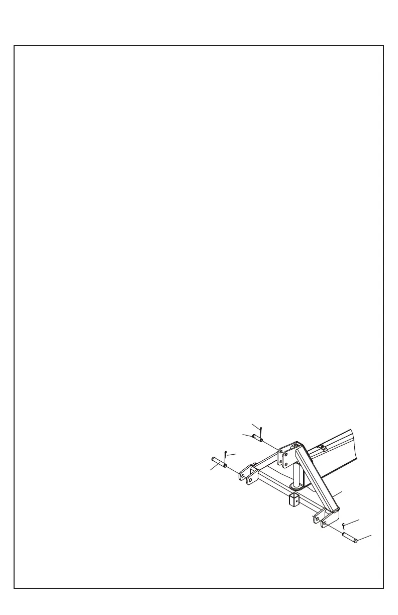
CATEGORY II
1. Place the lift arms between the lower link
brackets. Secure with lower locking bolts (17) and
insert insurance "R" 1/8 (33).
2. Connect the bar of the tractor's third point hitch in
the hole top box hitch coupling (4) using the top
category II coupling pin (16). Secure with "R" 1/8
(33) pin.
3. Level the main frame by adjusting the length of
the bar of the third point of the tractor.
4. Lock the tensor of the lower drawbars of tractor to
prevent swinging of the rear blade.
CATEGORY II QUICK HITCH
1. Secure the lower locking bolts (17) using a hub
lower engagement pin * 1 7/16 "OD and insert
insurance" R "1/8 (33).
2. Place the pin in top of category II coupling (16)
and upper bushing coupling pin * 1 1/4 "OD Catego-
ry 2 lug engaging the top and secure with safe "R"
1/8 (33).
3. Back up tractor with the rapid 3-point hitch for
coupling engagement with picture of the rear blade
(4) ensure that the pins are aligned and centered
with the lower latch ears.
4. Lift the lower drawbars of tractor.
5. Level the main frame by adjusting the length of
the bar of the third point of the tractor.
6. Lock tensors of the lower tractor drawbars to
prevent swinging of the rear blade.
NOTE: The upper and lower bushing pin hitch are
not included with the of the rear blade.
NOTE: Some tractors may be necessary to remove
the drawbar. Ensure at least six inches away from
the rear blade to the tractor tires throughout the
operating range of the coupling table.
20
OPERATION
17
33
16
33
33
17
4
NB80-003
 Loading...