Page 3
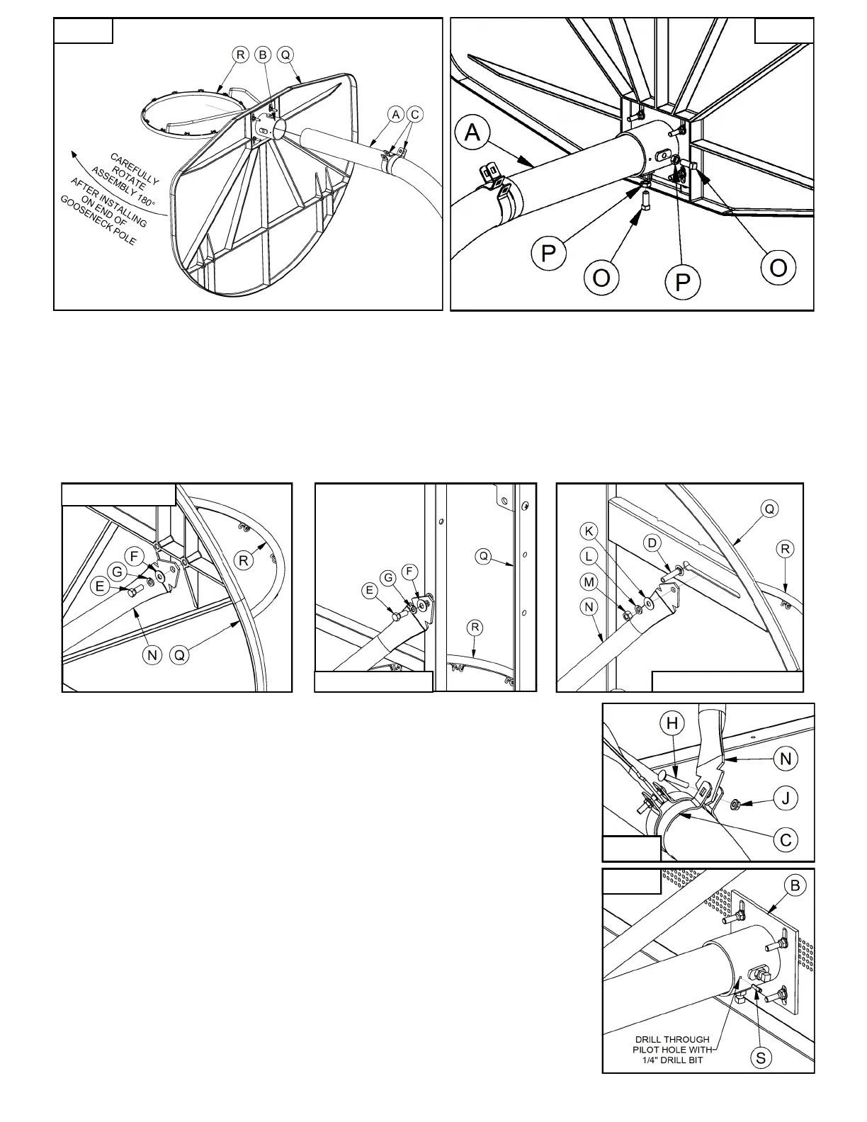
10. Referencing the illustrations below fasten Backboard Braces (N) to the Backboard (Q). Each model will
require different hardware to attach the Backboard Braces (N) to the Backboard (Q). BA475SS &
BA407G/U require 3/8” x 1” Hex Bolts (E), 3/8” Flat Washers (F), and 3/8” Lock Washers (G).
BA495 & BA47 require 7/16” x 2” Carriage Bolts (D), 7/16” Flat Washers (K), 7/16” Lock Washers (L),
and 7/16” Hex Nuts (M). Backboard Braces (N) will need to be bent on the ends to match the angles of the
Backboard (Q) and Band Clamps (C). Exact angle will depend on the Backboard (Q) model selected. This
can easily be accomplished in a number of ways, including contacting the end of the Backboard Brace (N)
on a concrete surface. See illustrations below.
12. Confirm Backboard (Q) and Rim (R) are still level before drilling a 1/4”
diameter hole into the Gooseneck Pole (A) using the pilot hole in the
Backboard Mounting Bracket (B) as a guide. Install the 1/4” X 1” Roll
Pin (S) into the hole you just drilled with a hammer to further reduce the
risk of rotation or movement. See Figure 7
13. Attach Net (R) and optional Pole Pad (U) if applicable. The system is
now ready for play.
Figure 4 Figure 5
MODEL:BA475SS
MODEL:BA495 OR BA47 MODEL:BA407G/U
11. Attach the other ends of the Backboard Braces (N) to the Band Clamps (C)
using the 5/16” x 2” Carriage Bolts (H) and 5/16” Flange Nuts (J). See
Figure 6.
Figure 6
Figure 7
 Loading...