EasyManua.ls Logo

Bison PR98GHT - User Manual

Bison PR98GHT
8 pages
Print Icon
To Next Page IconTo Next Page
Loading...
1
Inspect all contents prior to installation. Report any missing parts to dealer immediately.
Read all instructions before proceeding.
P A R T S L I S T
**Packaged Separately
Item Qty Description Item Qty Description
A 1 Ground Anchor** Q 1 5/8” X 5” Hex Bolt
B 1 Pole R 4 5/8” X 1 1/2” Hex Bolt
C 1 Lower Arm S 4 5/8” Lock Washer
D 2 Upper Arm T 1 3/4” X 2” Hex Bolt
E 1 Crank U 1 1/4” X 3” Hex Bolt
F 1 Height Gauge V 3 1/4X 2 1/2” Hex Bolt
G 1 Pointer W 5 1/4” Hex Nut
H 1 Pole Cap X 1 Backboard** (see table on page 4)
I 1 1/2” X 6 1/2” Hex Bolt Y 1 Backboard H-Frame** (see table on page 4)
J 1 1/2”-13 Deformed Lock Nut Z 8 5/16" X 1" Machine Screw
K 1 3/4” X 7” Hex Bolt AA 8 5/16" Lock Washer
L 2 3/4Hex Nut BB 8 5/16" Hex Nut
M 2 3/4” Flat Washer CC 1 BA32 Rim** (BA39U optional)
N 2 5/8” X 11” Hex Bolt DD 1 Pole Pad** (If applicable)
O 3 5/8” X 12” Hex Bolt EE 1 Backboard Padding** (If applicable)
P 6 5/8Lock Nut
Date: 4/1/2020 Rev: 1 B.A. N.J.C. File: \ publisher\Hangtime\Hangtime Pole System Ref#: 920444
Warning!
Improper installation, maintenance or use may cause product failure and serious personal injury.
Two or three people in good physical condition and capable of lifting at least 90-100lbs each are
recommended for safe installation and assembly.
 
6” 
 PR98GHT, PR98GHTJR, PR98SHT,
PR98SXLHT, PR98UHT, PR98UHTJR, HT6060G, HT6060GS, HT6072G
Customer Service
(800) 247-7668
1. Remove the plugs from the bolt holes in the Ground
Anchor (A) and inspect the threads to make sure they
are in good condition. Re-install the plugs, they keep
concrete and debris from getting into the bolt holes
during installation.
2. Determine the footing location. When the Rim (CC) is
at 10’ height there is approximately 48” of safe play
area. Make sure that when installed the edge of the
Ground Anchor (A) is a minimum of 6” away from the
playing surface. Contact your local utility location
provider to avoid dangerous or inconvenient contact
with buried utilities. The footing should be 14”-18” in
diameter and 48”-50” deep. See Figures 1 & 2.
Figure 1
Question and Answer IconNeed help?

Do you have a question about the Bison PR98GHT and is the answer not in the manual?

Summary

Parts List

Safety Precautions

Installation Safety Requirements

Requires 2-3 people in good physical condition for safe installation.

Ground Anchor Installation

Ground Anchor Preparation

Inspect and prepare the Ground Anchor bolt holes for installation.

Footing Location and Specification

Determine footing location, ensuring 6" from playing surface, 14-18" diameter, 48-50" deep.

Required Tools and Concrete Mixing

Gather tools, mix concrete per manufacturer, vibrate to remove air bubbles.

Ground Anchor Placement and Leveling

Position and level Ground Anchor, ensuring it's 6" from hole edges and 1-3" above playing surface.

Pole Attachment and Assembly

Attaching the Pole to Ground Anchor

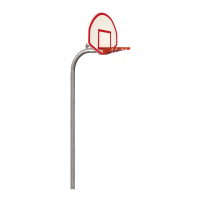
Connect Pole to Ground Anchor using specific bolts and nuts, ensuring free swivel.

Securing the Pole with Hex Bolt

Install 3/4" Hex Bolt and Nut to lock Pole; must remain until raised.

Lower Arm Attachment

Attach Lower Arm to Pole using 5/8" Hex Bolt and Lock Nut, ensuring free pivot.

Crank and Upper Arm Installation

Crank Mechanism Attachment

Attach Crank to Pole and Lower Arm using specified hardware.

Upper Arm Attachment

Attach Upper Arms to Pole using 5/8" Hex Bolt and Lock Nut, do not overtighten.

Backboard and Frame Assembly

Backboard H-Frame Assembly

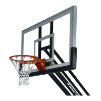
Assemble Backboard H-Frame to Backboard using machine screws, lock washers, and nuts.

Backboard to Arm Attachment

Lift and align assembled Backboard/H-Frame with Lower and Upper Arms, then attach.

Rim and Pole Final Assembly

Backboard H-Frame to Arm Attachment

Attach Backboard H-Frame to Lower and Upper Arms using specified hardware.

Backboard to H-Frame Attachment

Hang Backboard onto H-Frame and secure with carriage bolts, washers, and nuts.

Rim Installation

Install Rim using provided hardware, washers, and nuts; hand tighten initially.

Leveling Backboard and Rim

Level the Backboard and Rim, then tighten all hardware securely.

Pole Cap Installation

Install the Pole Cap onto the top of the Pole.

Securing Pole to Ground Anchor

Fasten Pole to Ground Anchor with 5/8" Hex Bolts and Lock Washers, replacing temporary bolt.

Height Gauge and Final Touches

Height Gauge Attachment

Attach Height Gauge to Lower Arm using Hex Bolt and Nut; assemble Pointer mechanism.

Adjusting Height Gauge

Crank system to 10', adjust Height Gauge to read 10', then tighten hardware.

Pole Pad and Backboard Padding

Install Pole Pad and Backboard Padding if applicable per included instructions.

Bison PR98GHT Specifications

General IconGeneral
BrandBison
ModelPR98GHT
CategorySports & Outdoors
LanguageEnglish

Related product manuals